Advertisement
Quick Links
PLEASE READ THIS MANUAL BEFORE ATTEMPTING TO OPERATE EQUIPMENT!!
1. Carefully lift the amplifier by the bottom cabinet edge out of the shipping carton. Place the
amplifier on a firm, level surface and carefully inspect it for shipping damage. Contact the
shipper immediately if any damage exists. Do not discard the carton or packing material.
2. Remove the twelve screws holding the cover on with a number 2 phillips screwdriver.
Carefully lift the cover off the amplifier. Save the screws to resecure the cover.
3. Locate the fuse pack with the two 12 amp fuses and fuse caps. If additional screws are
needed, they will be in the fuse pack also. NOTE: Fuses supplied are for 120/110/100V
operation. If you are rewiring the AL-811 for 240/230/220V operation, you must use 8
amp fuses. The AL-811X export model is pre-wired for 240V operation and is supplied with
8 amp fuses.
4. Remove the foam packing material (left side, front view) that secures the 811A tubes during
transit. Carefully unwrap the tubes. Do not dislodge the Aluminum shaft that is connected to
the rear input bandswitch wafer.
5. To install the tubes in the sockets be sure the large diameter pins line up with the two large
diameter holes in each socket. Do NOT rock or twist the tubes excessively during the
installation.
If the tubes are already installed, check the tubes for proper seating.
necessary, press the tubes down into their sockets with gentle force. Do not rock or twist the
tube(s) excessively. Also check that the anode caps are secure and did not come loose during
the unwrapping process.
6. The white ceramic anode connectors will have to be removed from the top metal cap of each
tube if it ever becomes necessary to remove the tubes from the amplifier. This can be a
difficult procedure because of the high clamping force of the internal springs in the anode
connector may hold it to the cap very tightly. The tube will break if direct upward or rocking
pressure is applied in an attempt to remove the connector. The safest way to remove the
ceramic connector is to lift the tube out of its socket. A twisting or spinning pulling motion
can then be applied while holding the ceramic connector firmly until the tube and connector
are separated. Repeat the procedure for the other tubes.
7. Install the cover with the vent holes to the left (near the tubes) by installing the back screws
first. Install all the screws loosely and tighten them only after all the screws are in place.
8. Install the fuses and fuse caps on the back of the unit. Read the manual to become familiar
with the operation of the AL-811 amplifier.
UNPACKING INSTRUCTIONS
If
Advertisement

Related Manuals for AMERITRON AL-811X


Summary of Contents for AMERITRON AL-811X
- Page 1 NOTE: Fuses supplied are for 120/110/100V operation. If you are rewiring the AL-811 for 240/230/220V operation, you must use 8 amp fuses. The AL-811X export model is pre-wired for 240V operation and is supplied with 8 amp fuses.
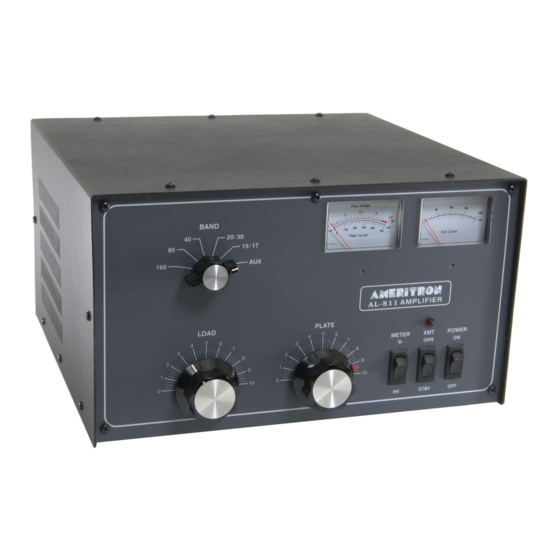
- Page 2 Domestic model(AL-811): 160, 80, 40, 30, 20, 17 and 15 meter bands 1. Fast Warm Up Time: The 811A tubes take Export model(AL-811X): 160, 80, 40, 30, 20, 17, 12 approximately 3 seconds to warm-up. and 10 meter bands. 2. Long Tube Life: The 811A tubes are long life, reliable transmitting tubes.
-
Page 3: General Information
A capacitive divider consisting of C27 and C28 is used to reduce AMERITRON the RF voltage and drive a rectifier circuit consisting of D17 and 116 Willow Road D18. -
Page 4: Installation
Do NOT place any books, The AL-811X (export model) is wired for 240V, 50/60 Hz magazines or equipment that will impede the free flow of air operation. - Page 5 INTERCONNECTIONS Connect the RF output of the transmitter to the RF IN Connect the shortest ground lead possible from a good earth connector on the rear of the AL-811 with 50 ohm coax. Use ground to the GND terminal. The best leads are solid any 50 ohm cable (RG-58 is fine) with PL-259 plugs.
- Page 6 TUNE-UP CW PROCEDURE With the exciter drive still at zero, place the HV-Ip switch in the Ip position. Observe the 750mA scale. It should Follow the instruction in numerical order. If the various meter read zero. Place the STBY-OPR switch in the OPR readings are different than the instructions, check the position.
- Page 7 IMPORTANT ADDITIONAL INFORMATION Authorized dealer: http://www.classicinternational.eu...
- Page 8 Authorized dealer: http://www.classicinternational.eu...
-
Page 9: Qsk Operation
QSK-5. relay effectively. Contact Ameritron for details on the QSK-5. The AL-811 will operate with full output on all WARC bands except 24.5 MHz. The AL-811X will operate with full output on all WARC bands. STANDARD FREQUENCY CONVERAGE AL-811 AL-811X 160 meters 1.8 - 2.0 MHz... -
Page 10: Periodic Maintenance
PERIODIC MAINTENANCE The high voltage present on the plate choke and air variable Remove the cover and connect a jumper wire from ground to the capacitors attract dust and dirt out of the air stream. It is anode connection of the tubes. NOTE: This is a safety wire particularly important that the high voltage areas at the bottom that must be installed when beginning service work and of the of the plate choke and the insulator on the air variable...
Need help?
Do you have a question about the AL-811X and is the answer not in the manual?
Questions and answers