Table of Contents
Advertisement
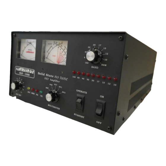
Ameritron ALS-1306
1200-Watt 160-6 Meter
T-MOSFET AMPLIFIER
The Ameritron ALS-1306 is 1200-watt PEP nominal output, 160- through 6-meter amateur radio band (1.8-54
MHz) solid-state amplifier. The compact 10" wide by 6-1/2" high amplifier package, with a depth of only 18",
fits nearly any station configuration. The attractive desktop amplifier unit weighs only 24 pounds. The ALS-
1306 meets or exceeds all FCC requirements governing amateur radio external power amplifiers.
Fan speed is regulated by temperature sensors, assuring conservative cooling with minimal noise. Protection
circuitry reduces power as transistors approach conservative thermal limits, and disables the amplifier before
the transistors exceed safe operating temperature limits.
The ALS-1306 uses eight 50-volt, conservatively rated, linear RF MOSFETS. These MOSFET's are primarily
designed for linear power amplifier applications, not class-C or pulse service. They provide exceptionally low
SSB distortion when compared to most other solid-state devices. Nominal driving power is 100-watts for 1200-
watts output (approximately 11 dB gain) on most bands.
T/R (transmit-receive) switching is through a pair of sequenced miniature relays on a plug-in module. The plug
in module facilitates relay servicing or maintenance. T/R switching time is approximately five milliseconds.
The T/R "Relay" control jack is well within the range of almost any transceiver or radio. The "Relay" jack has
an open circuit voltage of 13-volts, and closed circuit current less than 20 mA. Virtually any modern amateur
radio will directly key this amplifier.
This amplifier includes full metering using large easy-to-read conventional panel meters.
An external 50-volt 50-ampere regulated power supply powers the ALS-1306. The supply is wired for 240
VAC (200-260 VAC, 50-60 Hz, 15 amperes), but can be rewired for 120 VAC operation for lighter duty
operation.
ALS-1306 Exihibit VIII Page 1 / 27
Advertisement
Table of Contents

Related Manuals for AMERITRON ALS-1306


Summary of Contents for AMERITRON ALS-1306
-
Page 1: General Overview
This amplifier includes full metering using large easy-to-read conventional panel meters. An external 50-volt 50-ampere regulated power supply powers the ALS-1306. The supply is wired for 240 VAC (200-260 VAC, 50-60 Hz, 15 amperes), but can be rewired for 120 VAC operation for lighter duty operation. -
Page 2: Table Of Contents
SWR ..............................16 CIRCUIT BOARD DESCRIPTIONS ....................16 2KWF6 ............................16 BS2 ..............................16 CB2 ..............................16 MB1 ..............................16 PAM-606 (power amplifier module) Boards..................16 PD8 ..............................16 RJ45 ..............................17 RLY ..............................17 SWR ..............................17 SCHEMATICS AND INTERNAL WIRING ..................18 ALS-1306 Exihibit VIII Page 2 / 27... -
Page 3: Amplifier Features
Standard negative-going ALC output with front panel adjustment ALC metering and ALC LED indicator Fully-regulated external power supply Compact size 17.5” deep x 7” high x 10.5” wide Weight amplifier section 24 pounds ALS-1306 Exihibit VIII Page 3 / 27... -
Page 4: Installation
2. Insert the fuse and cap assemblies into the power supply’s fuse holders. The fuses lock in place with a slight turn. 3. Connect the power supply to the amplifier. 4. Be sure the amplifier power switch is turned off. ALS-1306 Exihibit VIII Page 4 / 27... -
Page 5: Station Ground
The ground lugs are for connections to a desktop ground buss system. A proper desk ground buss is a short, wide, conductor that runs the width of the operating position. All equipment should bond to that buss, unless a manufacturer specifies otherwise. ALS-1306 Exihibit VIII Page 5 / 27... -
Page 6: Coaxial Line Isolators
This can be a smaller cable, such as RG-58/U. Do not use or install an antenna tuner on this port. RF OUT To 50-ohm antenna, antenna tuner, power meter. This is the high power output. 50-ohm coaxial cable and system beyond must safely handle at least 1200-watts. ALS-1306 Exihibit VIII Page 6 / 27... -
Page 7: Power Supply
This port must pull low for transmit, and be open circuit when receiving. Relay control voltage from the ALS-1306 is 12 volts positive with only 15 mA current. You should always check your transceiver’s manual, but almost any standard transceiver directly interfaces with this amplifier. -
Page 8: Power Supply Features
Power Supply Features Efficient operation from 200-260 volts ac (12 amperes typical at full output power) Low standby and receive power drain, typically less than 100-watts with ALS-1306 attached and operational Generator and inverter friendly with acceptable powerline frequency range 40 to 400 Hz ... -
Page 9: Interconnection Wiring
Interconnection Wiring Interconnections Figure 2 ALS-1306 Exihibit VIII Page 9 / 27... -
Page 10: Amplifier Front Panel
The right-hand meter’s rightmost scale-arc (fig.2 ref 2B) is used for PEP reflected power, ALC power setting (power scale times ~ten), and combiner imbalance (power scale direct) using the upper scale numbers and pickets. Notice power calibrations are not evenly spaced. Lower scale numbers and pickets, because they ALS-1306 Exihibit VIII Page 10 / 27... -
Page 11: Initial Operation
Reflected power should remain very low, and PA current should increase slightly on both scales of the current meter (fig.2 ref 1A and 1B). No other LED’s should illuminate. ALS-1306 Exihibit VIII Page 11 / 27... -
Page 12: Operation
PA (power amplifier) or filter damage may occur. Ameritron guarantees to exceed FCC part 97.307 harmonic suppression standards, as of January 2013, inside amateur bands listed in the table above. Ameritron does not guarantee harmonic suppression or operation outside amateur bands. -
Page 13: Als-1306 Functional Overview
ALS-1306 Functional Overview The ALS-1306 is an amateur radio multiband radio frequency linear power amplifier. This device requires certification. This device complies with technical standards of CFR Title 47 part 97.317(a) and (b) as of April 2013. General Operation This linear amplifier covers the 160, 80, 40, 30, 20, 17, 15, 12, 10, and 6-meter amateur bands. Up to 100-watts exciter power is applied to relay RLY1 on circuit board RLY. -
Page 14: 2Kwf6 Lowpass Filter Assembly
The characteristics of linear high-voltage FET’s are very much like those of triode vacuum tubes. While this amplifier will run more than 1200-watts PEP output, linearity might suffer. Ameritron recommends running 1200-watts PEP or less for maximum linearity, although most amplifiers will remain clean above 1200-watts PEP. -
Page 15: Band Decoding
The CB2 board contains band-decoding systems. It also has a sensitive embedded frequency counter system. The frequency counter system in all ALS-1306 amplifiers, regardless of band selection mode, automatically disables operation between 25 and 28 MHz. This embedded logic function cannot be disabled or changed. -
Page 16: Swr
SWR mismatch, to an ideal 50-ohm resistive load. Circuit Board Descriptions There are eight basic circuit boards plus two power amplifier modules in the ALS-1306. The text below gives a brief description of each board’s function. -
Page 17: Rj45
The SWR board is on the rear panel in front of the RF output connector. It is a traditional 50-ohm directional coupler. The null adjustment is accessible through a rear panel hole. ALS-1306 Exihibit VIII Page 17 / 27... -
Page 18: Schematics And Internal Wiring
Schematics and Internal Wiring 2KWF6 output filter Figure 4 ALS-1306 Exihibit VIII Page 18 / 27... - Page 19 BSW2 bandswitch figure 5 ALS-1306 Exihibit VIII Page 19 / 27...
- Page 20 CB2 control board Figure 6A ALS-1306 Exihibit VIII Page 20 / 27...
- Page 21 CB2 control board Figure 6B ALS-1306 Exihibit VIII Page 21 / 27...
- Page 22 MB1 combiner board Figure 7 ALS-1306 Exihibit VIII Page 22 / 27...
- Page 23 PAM-606 PAM-606 power amplifier module Figure 8 ALS-1306 Exihibit VIII Page 23 / 27...
- Page 24 PD8 power divider Figure 9 RJ45 interface Figure 10 ALS-1306 Exihibit VIII Page 24 / 27...
- Page 25 RLY antenna relay Figure 11 SWR directional coupler Figure 12 ALS-1306 Exihibit VIII Page 25 / 27...
- Page 26 Power and Control Wiring 13 ALS-1306 Exihibit VIII Page 26 / 27...
- Page 27 PAM-606 power amplifier module Figure 8 ..................23 PD8 power divider Figure 9 ......................24 RJ45 interface Figure 10 .........................24 RLY antenna relay Figure 11......................25 SWR directional coupler Figure 12....................25 Power and Control Wiring 13......................26 TABLES Frequency Limits Table 1 ........................12 ALS-1306 Exihibit VIII Page 27 / 27...
Need help?
Do you have a question about the ALS-1306 and is the answer not in the manual?
Questions and answers
HOW TO HOOK UP ALS1306 TO FTDX 101 D RADIO
To connect the Ameritron ALS-1306 amplifier to the FTDX 101D radio, follow these steps:
1. Power Connection: Ensure the ALS-1306 is powered with 12 volts positive and 15 mA current.
2. RF Input Connection: Connect the IN connector of the ALS-1306 to the RF output of the FTDX 101D using a high-quality coaxial cable (RG-58/U or Mini-8 (RG-8X)).
3. RF Output Connection: Connect the RF OUT port of the ALS-1306 to your station’s power/SWR meter, antenna, or antenna matching device. Use Mini-8 or RG-8X cables (except for RTTY, where larger RG-8 is preferred).
4. Antenna Matching: The antenna tuner (if used) should be placed at the RF output side of the amplifier, not at the input.
5. Drive Power: Ensure the FTDX 101D does not exceed 100 watts peak envelope power when driving the ALS-1306.
6. Avoid Active Matching Devices: Do not install any active antenna matching devices on the input side of the amplifier.
Always check the transceiver manual for specific settings and ensure proper grounding and ventilation for safe operation.
This answer is automatically generated