Table of Contents
Advertisement
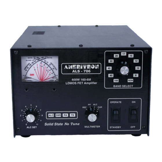
AMERITRON ALS-706/S
600 WATT 160-6 Meter NO TUNE
LDMOS-FET AMPLIFIER
INSTRUCTION MANUAL
WARNING!
NEVER APPLY POWER TO THIS AMPLIFIER WITH THE COVER REMOVED!
CONTACT WITH THE POWER SUPPLY VOLTAGES IN THIS AMPLIFIER CAN BE FATAL!
PLEASE READ THIS MANUAL BEFORE OPERATING THIS EQUIPMENT!
Factory
116 Willow Road
Starkville, MS 39759 USA
662-323-8211
Version 0
Printed in the USA
Advertisement
Table of Contents

Related Manuals for AMERITRON ALS-706


Summary of Contents for AMERITRON ALS-706
- Page 1 AMERITRON ALS-706/S 600 WATT 160-6 Meter NO TUNE LDMOS-FET AMPLIFIER INSTRUCTION MANUAL WARNING! NEVER APPLY POWER TO THIS AMPLIFIER WITH THE COVER REMOVED! CONTACT WITH THE POWER SUPPLY VOLTAGES IN THIS AMPLIFIER CAN BE FATAL! PLEASE READ THIS MANUAL BEFORE OPERATING THIS EQUIPMENT!
-
Page 2: Table Of Contents
RF Exposure Information ..........................23 ALS-600PS Voltage Settings ......................25 ALS-600SPS Switching Power Supply ....................26 ALS-600SPS Voltage Settings ......................26 ALS-706 Limited Warranty .......................... 28 Tables Table 1 Quick Start Fault Alarms ........................7 Table 2 Optional Radio Interface Cables ....................19 Table 3 Band Frequency Ranges ....................... - Page 3 Figures Figure 1 Basic Interconnection ........................7 Figure 2 Front Panel ........................... 15 Figure 3 ALS-706 Back Panel........................16 Figure 4 ALS-600PS Jumper Pins ......................25 Figure 6 ALS-600SPS Board Diagram ....................... 26 Manual Version 0 03-22-2021...
-
Page 4: Amplifier Features
Amplifier Features This amplifier provides the following standard features: 160 through 6-meter operation, full-power on six meters. One conservative linear-service rated 50 volt Dual LDMOS FET transistor. New push-pull stripline PA layout with exceptional VHF performance. Energy-efficient solid-state design greatly reduces heat, <100 watts power line draw on receive. -
Page 5: Quick Start
Quick Start Thank you for purchasing this amplifier system. The ALS-706 is a 600 watt nominal PEP output amplifier and power supply system. This amplifier covers 160 to 6 meters. Nominal drive power is 100 watts or less. This system will not and does not operate on the CB band. -
Page 6: Radio And Antenna Connections
Relay line to ground with a relay contact or transistor. Read your radio manual. Unless you have a very unusual radio, your radio will directly key the amplifier. 6.) The remote and radio band data connectors are specialized connections. They are for use with Ameritron supplied cables only. -
Page 7: Alerts
Alerts This amplifier has front panel alert codes using the SWR, PA, TX, warning LED’s and bandswitch band indicators. When a fault code appears, the amplifier is disabled. When an operating problem is corrected, operation is restored and alerts canceled by moving the front panel Standby/Operate switch to Standby. -
Page 8: Operation
7. The amplifier will shut off with an incorrect band selection, high antenna SWR (even for an instant), if safe thermal limits are reached, or with catastrophic failures. 8. The ALS-706 reads peak envelope power on forward and reflected RF power scales. With proper installation, basic operation is straightforward: 1.) Set the bandswitch to the desired band. -
Page 9: Introduction
Introduction Thank you for purchasing this amplifier system. The ALS-706 is a compact 600 watt nominal PEP output amplifier. It uses an external power supply system. This amplifier covers 160 to 6 meters. Nominal drive power is 100 watts or less. NOTE: This amplifier excludes all operation between 26 and 28 MHz. -
Page 10: General Operation
Light weight 13 lbs. An illuminated cross-needle meter monitors 50V line output voltage and current. The ALS-706 external power supplies contain 14 volt positive and negative supplies, as well as a 50-volt 25-ampere continuous (30-ampere peak) main supplies. The ALS-706 PA (power amplifier) module operates from 50 volts, giving a total dc supply rating of 1250 watts average power and 1500 watts peak dc power. -
Page 11: Power Line Requirements
Amplifier Overview The Ameritron ALS-706 is a solid-state, 600 watt nominal RF output power, 1.8 to 54 MHz amplifier. The ALS-706 meets or exceeds all FCC requirements governing amateur radio external power amplifiers. -
Page 12: Installation
amplifier. Relay switching time is approximately ten milliseconds. Radio adjustable TX delay should be set to 10 mS. This amplifier includes full metering using a large easy-to-read conventional cross- needle panel meter. The meter reads all critical parameters, including Forward and Reflected peak envelope RF power, voltage and, current. -
Page 13: Installation, Wiring, And Connections
Installation, Wiring, and Connections The ALS-600SPS switching power supply is factory wired for 100-130 VAC. The linear ALS-600PS is prewired for 120-125 VAC nominal voltage. Both use standard NEMA-5- 15P 15 ampere 120-volt plugs. The round center pin is the safety ground. Do not remove the safety ground. -
Page 14: Station Rf Ground
piece of equipment. They are for connection to a desktop ground bus system common to all equipment, if you prefer to use such a system. Independent ground wire connections are counterproductive. Never use RF isolators between the amplifier and radio. Never use long independent wires to external grounds. Never connect desk equipment to ground rods that do not bond into the mains entrance ground rod. -
Page 15: Front Panel Controls
Front Panel Controls Figure 2 Front Panel The front panel contains the following indicators and controls. To prevent damage, become familiar with the front panel before operating the amplifier. 1. MULTIMETER Right scale FET Module Current, Voltage, ALC, and Reflected Power. -
Page 16: Back Panel Connections
25 amperes. Maximum safe output is 600 watts peak; maximum safe peak reflected power is 125 watts. Back Panel Connections Figure 3 ALS-706 Back Panel POWER INPUT The power supply must be unplugged from the power mains before installing or removing this connector. -
Page 17: Interconnections
This port must pull low for transmit, and be open circuit when receiving. Relay control voltage from the ALS-706 is 14 volts positive with only 15 mA current. You should always check your transceiver’s manual, but almost any standard transceiver directly interfaces with this amplifier. -
Page 18: Optional Radio Interface Cables
6. The ALC line is optional. In general, transceiver internal ALC is all that is necessary. The ALC monitors the RF output power and reflected power supplied by the ALS-706 to the load. 7. Operate the bandswitch manually during initial testing. Do not connect band decoders, band data lines, or computer interfaces until initial tests are completed and the amplifier is functioning normally. -
Page 19: Operating Frequency Range
(power amplifier) or filter damage may occur. This amplifier has significantly cleaner output purity than FCC part 97.307 requirements when operated inside all amateur bands listed in the table above. Ameritron does not guarantee harmonic suppression or operation in applications outside standard amateur radio bands. -
Page 20: Warning Lights
Warning Lights The ALS-706 has two primary warning lights in the center of the front panel, SWR and PA. When SWR or PA warnings illuminate from an operating fault the amplifier defaults to a forced bypass mode. Operational faults and the forced bypass are reset by placing the amplifier in standby. -
Page 21: Initial Operation
Initial Operation For personal and equipment safety, double-check all wiring and connections () before turning power on. After verifying all power supply and amplifier connections, follow the procedures below: Place the MULTIMETER switch (fig. 2, ref. 6) in the HV position. The multimeter is the right-side scale on the panel meter (fig. -
Page 22: Alc Adjustment
On SSB, it will show as a slow warble or modulation of power levels, especially at the very start of voice transmissions. If ALC attack bounce is observed, the ALS-706 will require ALC gain adjustment. The ALS-706 has a small flat-blade screwdriver adjustment for setting ALC gain. This adjustment is accessible through a small hole located on the left cabinet side behind the front panel, near the panel meter. -
Page 23: Rf Exposure Information
RF Exposure Information 100W 600W 1200W Controlled Uncontrolled Controlled Uncontrolled Controlled Uncontrolled Frequency Antenna Distance Distance in Distance Distance in Distance Distance in BAND Gain dBi in Meters Meters in Meters Meters in Meters Meters 160M 2.000 80/75M 4.000 7.000 10.2 10.2 14.4... -
Page 24: Table 6 Approximate Antenna Gain For Some Common Antennas
CFR Title 47 Part 97.13© (as of Apr. 1, 2020) requires the amateur operator to be in compliance with the radio frequency exposure requirements. The chart Table 5 above is a calculation of distances in meters for several different antenna gains using the formulae in the bulletin. -
Page 25: Als-600Ps Voltage Settings
ALS-600PS Voltage Settings Before opening up the ALS-600PS make sure the supply is unplugged. On the ALS- 600PS there are several solder on jumpers to set the line voltage range. Change the jumpers only if the line voltage is low. For most cases, unless you need to change over to 220VAC there should not be a need to change the jumpers. -
Page 26: Als-600Sps Switching Power Supply
ALS-600SPS Switching Power Supply ALS-600SPS Voltage Settings When opening up the ALS-600SPS make sure it is unplugged and has been off for a while to make sure the capacitors have been discharged. Some of the capacitors can have a charge of 300-400VDC. The ALS-600SPS will only need to be changed when switching between 120 and 240VAC. -
Page 28: Als-706 Limited Warranty
116 Willow Road Starkville, MS 39762 ALS-706 Limited Warranty Ameritron warrants to the original purchaser that this product shall be free from defects in material (except tubes and RF output transistors) or workmanship for one year from the date of original purchase.
Need help?
Do you have a question about the ALS-706 and is the answer not in the manual?
Questions and answers