Table of Contents
Advertisement
Ameritron ALS-1300
1200-watt
NO TUNE
TMOS-FET AMPLIFIER
The Ameritron ALS-1300 is a 160 through 15-meter 1200-watt output solid-state amplifier. An optional user-
installed MOD-10MK filter assembly extends operation to 12- and 10-meters. The ALS-1300 uses eight 50-
volt conservatively rated linear RF MOSFETS. These 50-volt linear FET's produce an exceptionally clean
signal compared to other solid-state amplifiers. Fan speed is regulated by temperature sensors assuring
conservative cooling with minimum noise.
Nominal driving power is 90 watts for 1200-watts output (approximately 11 dB gain) on most bands. The
compact 10.5" wide by 6.75" high amplifier package (depth only 19") fits nearly any station configuration. The
attractive desk-top amplifier unit weighs only 22 pounds.
An external 50-volt 50-ampere regulated switching power supply powers the ALS-1300. The supply is wired
for 240 VAC (200-260 VAC, 50-60 Hz, 15 amperes), but can be rewired for 120 VAC operation for lighter duty
operation.
1
Advertisement
Table of Contents

Related Manuals for AMERITRON ALS-1300


Summary of Contents for AMERITRON ALS-1300
- Page 1 NO TUNE TMOS-FET AMPLIFIER The Ameritron ALS-1300 is a 160 through 15-meter 1200-watt output solid-state amplifier. An optional user- installed MOD-10MK filter assembly extends operation to 12- and 10-meters. The ALS-1300 uses eight 50- volt conservatively rated linear RF MOSFETS. These 50-volt linear FET’s produce an exceptionally clean signal compared to other solid-state amplifiers.
-
Page 2: Table Of Contents
Table of Contents TABLE OF CONTENTS ........................2 AMPLIFIER FEATURES ........................3 POWER SUPPLY ..........................4 Power Line Requirements ..................................4 Power Supply Features..................................4 Power Supply Location ..................................4 GENERAL INFORMATION ........................5 Amplifier.......................................5 Power Supply ......................................5 INSTALLATION............................5 Airflow........................................6 INTERCONNECTION WIRING......................7 AMPLIFIER REAR PANEL ........................8 FRONT PANEL ............................9 OPERATION............................10 MARS OR CAP OPERATION ......................11 INITIAL OPERATION .........................12... -
Page 3: Amplifier Features
Amplifier Features This amplifier provides the following standard features: • Eight conservatively rated, very linear 50-volt MOSFET transistors • Operational in a few seconds. No long filament warm-up time • Clean layout with easy-to-service modular construction • Front panel LEDs indicate band, faults, ALC and transmitting status •... -
Page 4: Power Supply
Power Supply The power supply for the ALS-1300 is a voltage regulated current limited supply. It contains 14-volt positive and negative supplies as well as dual 50-volt 25-ampere continuous (30-ampere peak) fully current limited supplies. Each PA (power amplifier) module in the ALS-1300 operates from the separate 50-volt sources, giving a total dc input power rating of 2500 watts to the power amplifier modules. -
Page 5: General Information
Have the same consideration for the ALS-1300 amplifier and power supply. Be sure the air inlet temperature is not substantially above normal room temperature. Ideally the air inlet temperature should be kept below 32° C or 90°... -
Page 6: Airflow
Warning: Do not block cooling air inlets and outlets! Never expose the amplifier to water or mist. Airflow The amplifier must have a clear area to the sides and top for proper airflow, and to the rear for interconnection wiring. It is especially important to avoid obstructions that block the air inlet on the top left and both lower sides. -
Page 7: Interconnection Wiring
Interconnection Wiring POWER SUPPLY FUSE ANTENNA, ANTENNA FUSE TUNERS, SWITCHES, FILTERS ALS - 1300 OUT IN REMOTE TRANSMITTER / TRANSCEIVER INTERCONNECTIONS Interconnections Figure 1... -
Page 8: Amplifier Rear Panel
3.) Connect the RLY line to the transceiver’s accessory RELAY or XMT port. This port must pull low for transmit, and be open circuit when receiving. Relay control voltage from the ALS-1300 is 12 volts positive with only 15 mA current. You should always check your transceiver’s manual, but almost any standard transceiver directly interfaces to this amplifier. -
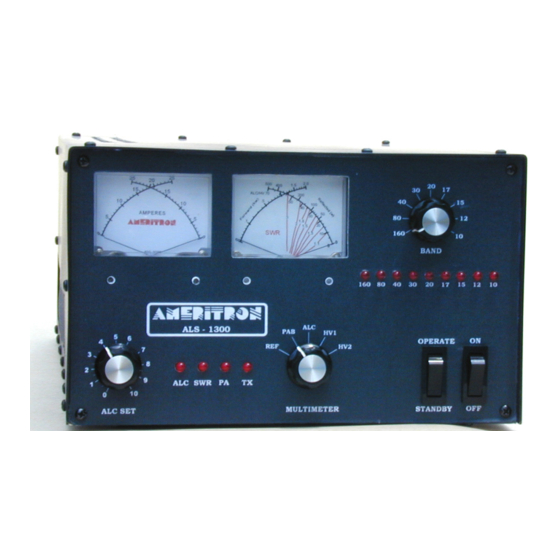
Page 9: Front Panel
Front Panel Amplifier Front Figure 2... -
Page 10: Operation
ALC SET (Fig 2.5 page 9) limits the output of the amplifier to a safe level when the rear ALC Jack is connected to the transceiver’s ALC input. The ALS-1300 produces an ALC control voltage of 0 to –4 volts DC. -
Page 11: Mars Or Cap Operation
ALC Monitors the ALC voltage on the rear panel ALC Jack. Meter reading is the 0-70 scale which corresponds to 0 to -7 volts. HV1 Monitors the operating voltage on the Power Amplifier Module “A”. Meter reads on the 0 to 70 scale. -
Page 12: Initial Operation
Operation on the 12 meter and 10 meter ham bands requires the installation of the optional MOD-10MK low pass filter assembly. The MOD-10MK is installed on export models of the ALS-1300, but is NOT included on amplifiers shipped within the US. Upon proof of a valid US amateur radio license, a MOD-10MK may be purchased from Ameritron. - Page 13 (fig.2 ref 1). No other lights should illuminate. 11. Briefly increase drive power (no more than 100 watts) until the ALS-1300 output is 1200 watts. 12. If ALC is connected between the amplifier and transceiver, rotate the ALS-1300 front panel ALC control counter-clockwise until the ALS-1300 output power just begins to drop.
-
Page 14: Circuit Boards
Circuit Boards There are ten basic circuit boards plus two power amplifier modules in the ALS-1300. The text below gives a brief description of each board’s function. 2KWF The 2KWF is a high power low pass filter. It is the very large board with large toroids and a few air wound inductors. - Page 15 RJ45 The RJ45 board mounts on the rear panel. It contains two RJ-45 jacks used for remote control operation. The RLY board contains two transmit and receive relays - one for RF output switching and the other for RF input switching. T/R relays activate with a low on terminals K (key) J1-3 and RJ1-7. The CB1 board contains the relay timing controls.
- Page 16 Bandswitch BS1 BS - 1 LED1 LED2 1N4001 LED3 1N4001 +12V LED4 1N4001 LED5 1N4001 LED6 1N4001 SW 1 +12V rear view LED7 1N4001 Remote LED8 LED9 +12V 7 July 2008 BS1 bandswitch figure 4...
- Page 17 Control Board CB1 CB1 rev2.1 090227 U1pin4 U1pin11 U4pin4 U4pin8 5.1v DC12V DC12V VR10 DC12V 4042 25k 40% LM358 REAR PANEL 4.7k 3906 4.7K 6.8k 2955 .1/50v 4.7k RL1 INP 4.7K 3904 DC12V LM358 TO MB 4.7k .1/50v .01/50v DC12V RL2 ANT 100k 6.8k...
- Page 18 Combiner 2000 watt CMB CMB 081217 rev0a 50 OHMS PA A 50 OHMS 50 OHMS PA B CMB combiner board Figure 6 Filter FL10 FL10 081210 130pF 130pF 130pF 130pF FL10 filter 10 meter Figure 7...
- Page 19 Metering Board MB1 -12V FWD SPEED REF SPEED R16 1m 40% 1m 40% CTRL 1N916 LM324 PIN 1...GND 1N916 2...12 - 4.7k 1N916 3...12 + 5.6k 4...FWD PWR + C3 2.5k 40% 4.7k 5...RFLCTD PWR 6...TRANSMIT LED 1N916 7...COMBINER LED 8...SWR LED 1N916 9...ALC VOLTAGE OUT...
- Page 20 PA Module PAM-600 081217 Revision 0a .001uF 470pF .1uF .1uF .33uF .33uF .1uF .1uF .001uF CONN 470pF 330pF .001uF .33uF .33uF 50VDC .1uF .1uF .33uF .33uF .47uF .33uF 100uF .33uF .1uF .1uF 470pF .001uF PAM power amplifier module Figure 9 Power Divider PD8 081126 rev0...
- Page 21 Interface Connections RJ45 RJ45 Rev0 090217 Pin8 Pin2 Pin4 Pin8 Pin6 Pin2 Pin4 Pin6 Pin3 Pin5 Pin7 Pin3 Pin7 Pin1 Pin5 Pin1 1/2W 0.1uF CONN RJ45 interface Figure 11 Relay Board RLA 081210 PA IN RADIO ANTENNA PA OUT MAY 21, 2008 RLY antenna relay Figure 12...
- Page 23 White 50V...
- Page 25 Reference figures and drawings Interconnections Figure 1 ............................7 Amplifier Front Figure 2............................9 2KWF output filter Figure 3 ..........................15 BS1 bandswitch figure 4............................16 CB1 control board Figure 5 ..........................17 CMB combiner board Figure 6 ..........................18 FL10 filter 10 meter Figure 7..........................
-
Page 26: Technical Information
Exhibit V Operational description HO82WUALS13 ALS-1300 Technical and Operational Overview The ALS-1300 is an amateur radio multiband radio frequency linear power amplifier. This device requires certification. This device complies with technical standards of CFR Title 47 part 97.317(a) and (b). - Page 27 transistor temperature increases. This bias feedback system keeps transistor quiescent current stable independent of transistor junction temperatures. These thermistors also feed a comparator that removes drive when transistor temperature becomes unsafe. The second set of thermistors, R1, monitor heatsink temperatures. Voltage from thermistor R1 regulates fan speed, increasing airflow as the heat sink warms.
- Page 28 IMITED ARRANTY Ameritron warrants to the original purchaser that this product shall be free from defects in material or workmanship for one year from the date of original purchase. During the warranty period, Ameritron (or an authorized Ameritron service facility) will provide free of charge both parts and labor necessary to correct defects in material or workmanship.
Need help?
Do you have a question about the ALS-1300 and is the answer not in the manual?
Questions and answers