Table of Contents
Advertisement
Quick Links
Advertisement
Table of Contents

Related Manuals for AMERITRON ALS-606S


Summary of Contents for AMERITRON ALS-606S
- Page 2 Notes: Version 0A...
-
Page 3: Table Of Contents
Contents Introduction ................................... 5 Amplifier Features................................. 6 Quick Start..................................7 Installation and Operation ............................. 7 Power Line or Mains Connections..........................7 ALS-600SPS................................ 7 ALS-600PS ................................8 Radio and Antenna Connections ........................... 9 Operation ................................10 Alerts.................................. 10 General Operation ............................... 13 Power Supply and Power Requirements........................ - Page 4 Filter 1KWF6..............................32 Bandswitch BSW3 ............................. 33 SWR Directional Coupler Board ........................33 Control Board CB2 ............................34 Metering Board MB2............................35 PA Module PAM-606 ............................36 Power Attenuator PD8m ............................ 36 Interface Connections RJ45 ..........................37 Relay Board ............................... 37 ALS-600PS Power Supply..........................
-
Page 5: Introduction
Kenwood serial data. With proper interface cables and data, this amplifier will automatically change bands in step with transceiver band changes. Automatic band selection using a band data port or band decoded bus requires purchasing an Ameritron interface cable for your radio. -
Page 6: Amplifier Features
Amplifier Features This amplifier provides the following standard features: 160 through 6-meter operation, full-power on six meters. Four conservative linear-service rated 50-volt MOSFET transistors. New push-pull stripline PA layout with exceptional VHF performance. Energy-efficient solid-state design greatly reduces heat, <100-watts power line draw on receive. -
Page 7: Quick Start
This includes operation on various line voltages, power supply operation, fuse selection, location, and power supply trouble shooting. Non-export versions of Ameritron ALS-600 series power supplies are wired and fused for 120Vac USA power mains, but all are modifiable to other standard power mains voltages. -
Page 8: Als-600Ps
mains supply, you may have to use a dedicated 120-V amplifier line, or rewire the supply and use 240-volt mains. With 120Vac mains at 600-watt nominal RF output, current draw is approximately 12 amperes on steady carrier. Peak line current is typically much less than 8 amperes at 600 watts PEP on SSB voice. -
Page 9: Radio And Antenna Connections
Unless you have a very unusual radio, your radio should directly key this amplifier. Avoid using external interfaces with relays. Amplifier relay switching time is approximately 10-12 mS. The remote and radio band data connectors are specialized connections. They are for use with Ameritron supplied cables only. Version 0A... -
Page 10: Operation
Operation Before attempting operation: This amplifier is optimized for 50-ohm loads. Be sure your antenna system 50-ohm SWR is as low as possible. As SWR increases from 1:1, either heat or distortion will increase. Be sure your antenna system, including any switches, baluns, matching circuits, or lighting protection devices, are in good condition and will safely handle high power. -
Page 11: Table 1 Quick Start Fault Alarms
The following table applies to faults: Warning Warning Fault Cause or Cure light Steady light Flash Antenna Reflected High antenna Power intermittent antenna or feed line connection SWR, PA Band Wrong filter Exciter amplifier incompatible band, filter failure Filter input SWR PA, TX PA FET too hot Excessive power for duty cycle... -
Page 12: Figure 1 Quick Starts Typical Wiring
Figure 1 Quick Starts Typical Wiring Version 0A... -
Page 13: General Operation
200 and 250 volts, 50/60Hz (6 amperes typical at full carrier power). A unique "buck-boost" winding allows compensation for up to six different power line voltages centered on 115 and 230 volts. This versatile Ameritron feature maintains optimum... -
Page 14: Power Line Requirements
1250 watts average power and 1500 watts peak dc power. The 12-volt supplies are for illumination, bias, and control functions. Power supply to amplifier interconnections are through a heavy-duty cable using reliable Cinch Jones connectors. Power Line Requirements This amplifier ships wired for a nominal mains voltage of 120 Vac with either supply. Maximum power line current at full power output is 12 amperes at 120 volts. -
Page 15: Amplifier Overview
Amplifier Overview The Ameritron ALS-606 is a solid-state, 600-watt nominal RF output power, 1.8-54 MHz amplifier. The ALS-606 meets or exceeds all FCC requirements governing amateur radio external power amplifiers. The ALS-606 uses four low-distortion MRF-150 (or equivalent) SSB RF power transistors in push-pull parallel. -
Page 16: Installation
Installation Please look your amplifier and power supply over carefully. Observe the air inlet and outlet ventilation holes. Facing the amplifier front panel, the cooling air inlets are on the top left and lower right side, including the right hand side cabinet bottom. Warm air exits vents at the cabinet rear. -
Page 17: Station Ground
15P 15-ampere 120-volt plugs. The round center pin is the safety ground. Do not remove the safety ground. CAUTION! Before connecting the power supply to an electrical outlet, always be sure you have completed the following four steps: 1. Insert the 15-ampere 250V fuses into the two black fuse caps. 2. -
Page 18: Safety And Lighting Grounding
Safety and Lighting Grounding The power supply cabinet grounds through a safety ground pin on the power plug. This system depends on a properly wired power outlet. Lightning protection grounds do very little good at the operating desk. Lightning protection grounds belong at the antenna cable entrance to the building. Station ground rods must always electrically connect through low impedance and resistance conductors to the power line entrance ground. -
Page 19: Operating Frequency Range
This amplifier has significantly cleaner output purity than FCC part 97.307 requirements (January 2016) when operated inside all amateur bands listed in the table above. Ameritron does not guarantee harmonic suppression or operation in applications outside standard amateur radio bands. -
Page 20: Warning Lights
Most non-amateur services prohibit use of non-commercial radio equipment. This amplifier automatically prevents operation between 25 and 28 MHz. Operation in the 25- 28 MHz range is not available with this product, irrespective of licensing or end-use. Warning Lights The ALS-606 has two primary warning lights in the center of the front panel, SWR and PA. -
Page 21: Interconnection Wiring
Interconnection Wiring Figure 2 Amplifier Interconnection Version 0A... -
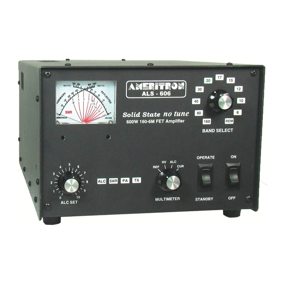
Page 22: Front Panel Controls
Front Panel Controls Figure 3 Front Panel The front panel contains the following indicators and controls. To prevent damage, become familiar with the front panel before operating the amplifier. 1. MULTIMETER Right scale FET Module Current, Voltage, ALC, and Reflected Power. -
Page 23: Back Panel Connections
amplitude carriers like a steady CW carrier, when PEP and average powers are equal. PEP is the highest average power during one (or more) radio frequency cycle(s) at the modulation envelope crest. The meter’s rightmost scale-arc indicates PEP reflected power in watts on the upper scale numbers and pickets. - Page 24 50-ohm coaxial cable and system beyond this connector must safely handle at least 600-watts. RADIO INTERFACE This connector is for use with Ameritron radio interface cables. It allows automatic band selection (following the radio). It also provides amplifier actuation in transmit mode with some radios.
-
Page 25: Initial Operation
600-watt rated Power/SWR meter, antenna, or antenna matching device. Good quality Mini-8 or RG-8X cables are acceptable for anything but RTTY use, although larger RG-8 style cables are normally preferred. The antenna matching system, or antenna tuner, must connect to this port. Connect the RF IN connector to your transceiver. -
Page 26: Alc Adjustment
change moving between 30 and 20, 17 and 15, or 12 and 10-meter selections since these band groups share a common filter in each pair. Set the BAND switch (Figure 3, #2) to a band where you have a good 50-ohm high- power load connected. -
Page 27: Power Supply Line Voltage Settings
threshold. This overshoot, dip, and recovery is caused by slow radio ALC response time. Excessive ALC control loop gain aggravates power bounce. ALC attack bounce shows on a steady carrier (such as RTTY, CW, or FM) as a high initial peak power reading followed by a deep null. The deep null is followed by a slow settling to the desired power level. -
Page 28: Als-600Sps Voltage Settings
ALS-600SPS Voltage Settings When opening up the ALS-600SPS make sure it is unplugged and has been off for a while to make sure the capacitors have been discharged. Some of the capacitors can have a charge of 300-400VDC. The ALS-600SPS will only need to be changed when switching between 120 and 240VAC. -
Page 29: Attenuator Board
panel RELAY control line is held low (below 1 volt), exciter power is routed through input relay RLY1 to the PD8m power attenuator board. ATTENUATOR BOARD The attenuator board has two 3dB attenuators. A relay switches one attenuator out on six meters. -
Page 30: 1Kwf6 Low Pass Filter Assembly
1KWF6 Low Pass Filter Assembly The PAM-606 module connects directly to the 1KWF6 circuit board assembly through a 50-ohm cable. Power enters the filter system through a directional coupler consisting of current transformer T2, capacitors C36-38, C40-42, and resistors R4, 5 and 6. This directional coupler detects termination errors at the filter’s power amplifier side. -
Page 31: Cb2
The CB2 is located on the amplifier side between the band selector and power jack, below the attenuator board. The CB2 control board provides most control functions, including bias, fan speed, overload, wrong-band protection, and transmit-receive relay sequencing. It is the hub for nearly all functions, including external interfaces, power metering, and 12-volt busses. -
Page 32: Schematics
Schematics Filter 1KWF6 Figure 7 1KWFL6 Filter Board Version 0A... -
Page 33: Bandswitch Bsw3
Bandswitch BSW3 Figure 8 Bandswitch BSW3 SWR Directional Coupler Board Figure 9 SWR Power Sensor Board Version 0A... -
Page 34: Control Board Cb2
Control Board CB2 Figure 10 Control Board CB2 Part 1 Figure 11 Control Board CB2 Part 2 Version 0A... -
Page 35: Metering Board Mb2
Metering Board MB2 Figure 12 Meter Board MB2 Version 0A... -
Page 36: Pa Module Pam-606
PA Module PAM-606 Figure 13 PA Module PAM-606 Power Attenuator PD8m Figure 14 Attenuator PD8m Version 0A... -
Page 37: Interface Connections Rj45
Interface Connections RJ45 Figure RJ-45 Interface Board Relay Board RLA 081210 PA IN RADIO ANTENNA PA OUT MAY 21, 2008 Figure 15 TR Relay Board Version 0A... -
Page 38: Als-600Ps Power Supply
ALS-600PS Power Supply Figure 16 ALS-600PS Power Supply Version 0A... -
Page 39: Figure 17 Als-600Ps Board
Figure 17 ALS-600PS Board Version 0A... -
Page 40: Als-600Sps Switching Power Supply
ALS-600SPS Switching Power Supply VOLT CURRENT LAMP RED/WHT B15 +14V BLUE BLUE B12 -14V .01 uF .01 uF J1.2 J1.3 J1.4 FROM J1.5 CABLE J1.6 J1.7 J1.8 BLUE J1.11 .01uF RELAY 1 B1 AC/N .01uF AC CORD 10 OHM 10 WATT .01uF YELLOW B2 AC/L... -
Page 41: Figure 19 Als-600Sps Ac/Dc Section
MAX=31A IRFP460 at 10 Min AC/N 50V/20A SS CD14 10U/16V AC /N 30A/250V ~ T300-26 10D241 DEF30JP C 13 4.7U/250V 2222A 103/1KV 102/1KV IRFP460 102/250V~ C 14 EEL22 474/300V~ 2907A 47/5W S B358 C 18 102/250V~ 104/50V 103/1KV 100R/5W 102/1KV DEF30JP 10D241 R 10... -
Page 42: Figure 21 Als-600Sps Board Ac/Dc Section 2
470UH EC36 680K AC 90 ~ 264V N.L=17.5V 104/300V 4.7U/400V 4.7U/400V 8*12 0.5A 680K 750K DR6*8 1A/250V~ ES3D 1207 220K 1210 750K 1208 470U/25V 220U/25V BYD57ZK 4.7R BYD57ZD 1206 PL1A PC817 22U/50V 2.2K 4.7R 104/50V 2SK2645 LD7535B UTC431 3.32k GATE SENSE PL1B 100K... - Page 43 NOTES: Version 0A...
-
Page 44: Als-606 Limited Warranty
(c) A detailed description of the problem, including details on the equipment. Deliver the product to the Ameritron or the nearest authorized service facility, or ship the same in its original container or equivalent, fully insured and shipping charges prepaid.
Need help?
Do you have a question about the ALS-606S and is the answer not in the manual?
Questions and answers