Table of Contents
Advertisement
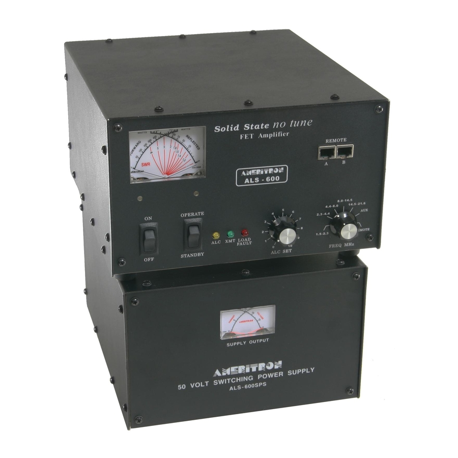
The Ameritron ALS-600 is a 600 watt output, solid state, linear amplifier using state-
of-the-art, high voltage, RF TMOS FET devices in the power output section. The
ALS-600 provides continuous frequency coverage from 1.5 through 22 MHz with no
tuning adjustments. Broad band 5 pole low pass filters provide output harmonic
suppression in excess of all FCC requirements. Export modifications are available to
extend operation up to 30 MHz with a copy of a valid amateur license.
The ALS-600 uses four MRF-150 FET's operating a 50 volts in a double ended
push-pull parallel output configuration. High quality RF components combine with
an accurate peak detecting directional coupler, front panel adjustable ALC circuit
with automatic SWR fold-back, and one switch frequency selection to make this one
of the easiest to operate amplifiers available. The matching power supply, ALS-
600PS, is shipped factory wired for 120 volt, 50/60 Hz power mains and is easily
converted to other supply voltages between 100 and 240 volts.
PLEASE READ THIS MANUAL BEFORE OPERATING THIS EQUIPMENT !
Version 2 Printed
in U.S.A.
116 Willow Road
116 Willow Road
116 Willow Road
116 Willow Road
Starkville, MS 39759 USA
Starkville, MS 39759 USA
Starkville, MS 39759 USA
Starkville, MS 39759 USA
662-323-8211
662-323-8211
662-323-8211
662-323-8211
A M E R I T R O N A L S - 6 0 0
6 0 0 W A T T N O T U N E
T M O S - F E T A M P L I F I E R
I N S T R U C T I O N M A N U A L
Advertisement
Table of Contents

Related Manuals for AMERITRON ALS-600


Summary of Contents for AMERITRON ALS-600
- Page 1 I N S T R U C T I O N M A N U A L The Ameritron ALS-600 is a 600 watt output, solid state, linear amplifier using state- of-the-art, high voltage, RF TMOS FET devices in the power output section. The ALS-600 provides continuous frequency coverage from 1.5 through 22 MHz with no...
-
Page 2: Table Of Contents
RTTY, FM and Other High Duty Cycle Operation ........... 13 AM Operation.....................…..14 Drive Power Requirements ...............…..14 Amplifier Operation................:....…..15 Periodic Maintenance..................…..16 ALS-600 Parts Lists & Schematics................…. 17 Meter/ALC Board..................…. 17 PA Board..............……........19 Output Filter Board..................…..20 LED Board................:....…..22 SWR Detect Board...................….. -
Page 3: Amplifier Features
12 volt auxiliary jack. This jack supplies +12v to operate low current Thermal Overload Protection. The transmit relay in the amplifier is disabled if excessive heatsink temperatures are reached. Compact size. The ALS-600 weighs only 12.5 pounds and measures 6"H x 9.5"W x 12"D. -
Page 4: Power Supply Features
30 MHz with a copy of a valid amateur license. The ALS-600 uses four MRF-150 FET's operating at 50 volts in a double ended push-pull parallel output configuration. High quality RF components combine with an accurate peak... -
Page 5: Export Modifications
19-10600, along with a copy of your valid amateur license to Ameritron. There is charge for this kit. Export models are shipped with this modification installed. The ALS-600Y is the export for 115-130vac operation and the ALS-600X is the export model for 220-240 operation. -
Page 6: Alc (Automatic Level Control)
The ALC circuit functions by using a comparator (IC103A) to reduce the exciter drive power if the output power of the ALS-600 exceeds a preset value. The ALC circuit also reduces the drive power if the SWR increases while operating with the ALC controlling the amplifier output power level. -
Page 7: Thermal Overload
ALC control systems requiring less than 10 volts. Thermal Overload The ALS-600 has a built in thermal cut-out that by-passes the amplifier if excessive heat sink temperature is produced. This circuit minimizes the risk of excessive temperature damage to the FET's and other components. -
Page 8: Swr Considerations
The TMOS FET devices used in the ALS-600 have nearly the same momentary overload tolerance as vacuum tubes. The low pass output network in the ALS-600 is much broader in bandwidth and less sensitive to load changes than the networks used in tube type amplifiers. -
Page 9: High Voltage Section
Refer to the chart on below for the proper location of the primary wiring. This chart lists the proper jumper connections for different ranges of MAXIMUM line voltage. The standard line voltage in the USA is NOT 110 and 220 volts. It is almost ALWAYS above 120 volts or 240 volts. -
Page 10: Low Voltage Circuits
Bias/ w attmeter board in the ALS-600. This low voltage circuit is protected by a 2 ampere fuse (F602) located on the power supply printed circuit board. -
Page 11: Grounding
Caution: The ALS-600 is not designed for operation for 12 Vdc operation. The ALS-600PS power supply is designed to match the ALS-600 amplifier. The ALS600PS provides 50 volts do at 25 amperes along with 12 volts positive and negative at low current for the control and bias circuits of the amplifier. -
Page 12: Interconnections
Interconnections Connect the RF output (ant) of the exciter to the RF IN (SO-239) of the ALS-600 with a good quality 50 ohm cable capable of handling 100 watts. Connect the station antenna system to the RF OUT (SO-239) connector with 50 ohm coax that will safely carry 600 watts. -
Page 14: Operation
Operation This amplifier is equipped with a switch on the front of the Amplifier's Power Supply labeled Normal/RTTY. This switch is used in the normal position for SSB and CW operation. The RTTY position is used for continuous carrier modes. This position will limit the voltage to about 42Vdc no load. -
Page 15: Cw Operation
The high voltage power supply can be reduced to increase the efficiency at lower output levels. At 30 volts the ALS-600 will deliver 275 watts of output power. This will allow a 100% duty cycle with any fan delivering more than 40 CFM at .08" of static pressure, such the EBM W2S107-AD21-39, or a 5 minute on, two minute off duty cycle with the standard fan. -
Page 16: Amplifier Operation
Drive Power Requirements The ALS-600 requires less than 100 watts of drive to produce full output power. Exceeding 100 watts of drive for long periods of time may cause component failures. Exceeding 100 watts of drive for short periods will cause distortion and increase the bandwidth of the transmitted signal. -
Page 17: Periodic Maintenance
A soft bristled brush and a small amount of alcohol can be used to clean stubborn dust from the fan screen or the other components. Be careful not to get any cleaning compounds on the relay contacts or the switches. Ameritron has a technical information sheet on relay and switch maintenance. -
Page 18: Als-600 Parts Lists & Schematics
ALS-600 Parts Lists & Schematics Meter/ALC Board 50-0600-1 Designator Description Part number C101,102,104,105,109, 0luF 50v disc 200-0416 107,112-115,117-123 C103,106 2.2uF 50v radial lead electrolytic 203-0225 C108,116 47uF 50v tantalum 203-0530 C110,111 not used D101 not used D102-105,107 1N34A diode 300-0346 D106 5.lv 1/2w Zener diode 1N4734... -
Page 20: Pa Board
PA Board 50-0600-2 Designator Description Part Number C201-203,217 not used C204-207,209-212 1 uF 50V disc 200-0745 C208 470 pF 500V DM 15 208-5440 C213,214,220-226 .33 uF 100V multilayer 205-1334 C215 47 uF 100V mylar 201-1474 C216 100 uF 100V radial lead electrolytic 203-1007 C218,219,232,233 360 pF 500V... -
Page 21: Output Filter Board
Output Filter Board 50-0600-3 Designator Description Part Number C301,308 not used C302,307 180 pF* 1000v CDV-30 208-6181 C303,309 270 pF* 1000v CDV-30 208-6271 C304,310 360 pF* 1000v CDV-30 208-6361 C305,311,319 680 pF* 1000v CDV-30 208-6681 C306,312,317 1500 pF* 1000v CDV-30 208-6152 C313,314 160 pF* CDV-30... -
Page 23: Led Board
LED Board 50-0600-4 Designator Description Part Number CR401 Green LED 320-0500 CR402 Yellow LED 320-0300 CR403 Red LED 320-0522-1 J401 10 pin header 612-0110 R401 470 ohm 1/4 watt 100-2470 R402 1k Potentiometer 105-1301... -
Page 24: Swr Detect Board
SWR Detect Board 50-0600-5 Designator Description Part Number C501,502 150 pF 1kV disc cap 200-2150 C503 not used C504 33 pF 1 kV Disc 200-2033 C505,506 .01 uF 50 Vdc 200-0416 C507 3-12 pF 500V TrimCap 200-0416 D501,502 1N34A or equiv. 300-0346 R501 3.3k 1/4 watt... -
Page 25: Als-600 Chassis Components
Components ALS-600 Chassis Designator Description Part Number 4.5" fan 410-3138 for B 1 fan filter screen 410-4600 Cl-C5 .01 50v disc capacitor 200-0416 C6-C7 .01 250Vac capacitor 200-2122 .01 kV disc capacitor 200-2121 J1,J2 SO-239 jacks 610-2126 J3-J5 phonojacks 600-1225... -
Page 26: Als-600Ps Parts Lists & Schematics
ALS-60OPS Parts Lists & Schematics Power Supply Board 50-0600-6 Designator Description Part Number C603 2200uF 25v radial lead 203-0207 C604 220uF 25v radial lead 203-0565 D601-603 1N4007 or equiv. 300-0266 F601 2 amp slow blow NIDL type 755-1102 F602 2 amp fast blow 755-1150 R601 10 ohm 1/2 watt... -
Page 27: Als-600Ps Chassis Components
ALS-600PS Chassis Components Part Number Designator Description 410-3583 3" muffin fan 410-4584 for B2 fan guard 203-0680 15000 uF 80 We capacitor & mounting bracket 200-2122 C3,4 0luF 250 Vac disc capacitor 300-9646 50 amp bridge rectifier 755-1102 F601 2 amp slowblow IvIDL type 755-1149 F602 2 amp AGC... - Page 28 USA 662-323-8211 LIMITED WARRANTY Ameritron warrants to the original purchaser that this product shall be free from defects in material (except tubes and RF output transistors) or workmanship for one year from the date of original During the warranty period, Ameritron (or an authorized Ameritron service facility) will provide free of charge both parts (except tubes and RF output transistors) and labor necessary to correct defects in material or workmanship.
Need help?
Do you have a question about the ALS-600 and is the answer not in the manual?
Questions and answers