Table of Contents
Advertisement
Quick Links
ALS-500M
ALS-500M Features ........................................................................................................1
General Information.........................................................................................................2
Load Fault Circuit................................................................................................2
Bias Control Circuits ...........................................................................................2
Drive Power .........................................................................................................2
Supply Voltage ....................................................................................................3
SWR Considerations............................................................................................3
Periodic Maintenance ..........................................................................................3
Technical Assistance ...........................................................................................3
Export Modifications...........................................................................................4
Installation .......................................................................................................................4
Location ...............................................................................................................4
Power Requirements............................................................................................4
Fuse Holder Installation.......................................................................................5
Auxiliary Battery Installation ..............................................................................5
Grounding........................................................................................................................6
Unibody Vehicles ................................................................................................6
Frame-Type Vehicles...........................................................................................6
Interconnections...............................................................................................................8
Operation .........................................................................................................................9
ALS-500M Parts List.......................................................................................................10
Combiner Board Parts List ..................................................................................10
Power Amplifier Board Parts List .......................................................................11
Output Filter Board..............................................................................................13
Bias Board Parts List ...........................................................................................14
TABLE OF CONTENTS
Instruction Manual
Advertisement
Table of Contents

Summary of Contents for AMERITRON ALS-500MXCE
-
Page 1: Table Of Contents
ALS-500M Instruction Manual TABLE OF CONTENTS ALS-500M Features ......................1 General Information......................2 Load Fault Circuit....................2 Bias Control Circuits ...................2 Drive Power ......................2 Supply Voltage ....................3 SWR Considerations....................3 Periodic Maintenance ..................3 Technical Assistance ...................3 Export Modifications...................4 Installation ........................4 Location .......................4 Power Requirements....................4 Fuse Holder Installation..................5 Auxiliary Battery Installation ................5 Grounding........................6... -
Page 2: Als-500M Features
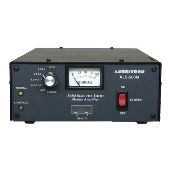
ALS-500M Instruction Manual ALS-500M FEATURES Rugged devices. The ALS-500M uses four rugged linear RF power devices. Fast warm-up time. The ALS-500M has no vacuum tubes to warm-up. No tune operation. Tuning adjustments are not necessary. A simple one knob selector switch permits operation on frequencies between 1.5 and 21.6 MHz. -
Page 3: General Information
ALS-500M Instruction Manual GENERAL INFORMATION Load Fault Circuit The ALS-500M features a load fault trip circuit that bypasses the amplifier if the amplifier frequency switch is set to a lower frequency range than the exciter or if the load reflected power exceeds 70-100 watts. -
Page 4: Supply Voltage
Be careful not to get any cleaning compounds on relay contacts or in switches. If it becomes necessary to perform maintenance on any switch or relay contact Ameritron. Ameritron has free technical support for customers that wish to service their own equipment. -
Page 5: Export Modifications
19-10600 export modification kit along with a copy of your valid amateur license to the Ameritron. There is a charge for this kit. Export models are shipped with this modification installed and have an "X" following the serial number. -
Page 6: Fuse Holder Installation
After wiring is completed install the fuses. Auxiliary Battery Installation If possible, avoid the use of an auxiliary storage battery. Ameritron does not assume any liability and does not recommend the use of an auxiliary battery. The individual installation is left entirely up to the installer. -
Page 7: Grounding
ALS-500M Instruction Manual The battery should be securely mounted in a well ventilated area. The hydrogen gas that forms when the battery is charging can be explosive if trapped in a confined area. Remember that hydrogen gas rises, and it can be trapped in the top of any compartment. Vents must exit vertically above the area to be ventilated. - Page 8 ALS-500M Instruction Manual...
-
Page 9: Interconnections
ALS-500M Instruction Manual INTERCONNECTIONS 1. The negative battery lead must be disconnected from the battery post. 2. The positive battery terminal must be disconnected from the positive battery post. 3. Add a heavy ground strap from the engine block or the battery's negative lead to the chassis of the vehicle. -
Page 10: Operation
ALS-500M Instruction Manual OPERATION Follow these instructions in numerical order. Consult the manual for the exciter, if necessary. Be sure all electrical connections is properly wired and the vehicle is running with a fully charged battery. See the Installation instructions for wiring details. 1. -
Page 11: Als-500M Parts List
ALS-500M Instruction Manual ALS-500M PARTS LIST Combiner Board Parts List Designator Description Part Number C101,102 Capacitor, Trimmer, 500V, 3-12 pF 204-0150 C107,108 Capacitor, Ceramic Disc, 50v, .01 uF 200-0416 C109 Capacitor, Monolithic, 50v, .33 uF 205-2233 C103,106 Not used C104,105 Capacitor, DM15, 500 pF 208-5691 D101,102... -
Page 12: Power Amplifier Board Parts List
ALS-500M Instruction Manual Power Amplifier Board Parts List Designator Description Part Number C225,226 Capacitor, DM19, 500v, 360 pF 208-5688-1 C227,228 Capacitor, SM19, 500v, 750 pF 208-5668 C237,238 Capacitor, DM19, 500v, 820 pF 208-5381 C201,208,211,212-216, Capacitor, 50v, .33 uF 205-2233 229,230,235,236 C202,207,209,210,233,234 Capacitor, Ceramic Disc, .1 uF 200-0754... - Page 13 ALS-500M Instruction Manual...
-
Page 14: Output Filter Board
ALS-500M Instruction Manual Output Filter Board Designator Description Part Number C301,308 not used C302,307 *Capacitor, SM-19, 1000v, 180 pF 208-6181 C303,309 *Capacitor, SM-19, 1000v, 270 pF 208-6271 C304,310 *Capacitor, SM-19, 1000v, 360 pF 208-6361 C305,311,319 *Capacitor, SM-19, 1000v, 680 pF 208-6681 C306,312,317 *Capacitor, SM-19, 1000v, 1500 pF... - Page 15 ALS-500M Instruction Manual...
-
Page 16: Bias Board Parts List
ALS-500M Instruction Manual Bias Board Parts List Designator Description Part Number C401,406-421, Capacitor, Ceramic Disc, 50v, .1 uF 200-0754 C402-405 Capacitor, Tantalum, 50v, .47 uF 203-0530 D401,402 Diode, 1N4007 300-0266 D403 Diode, Zener, 5.6 v, 1N4734 301-4734 FB401-405 Bead, Ferrite, #43 412-1599 For IC401 Socket, 14 pin... - Page 17 ALS-500M Instruction Manual...
- Page 18 ALS-500M Instruction Manual ALS-500M Chassis Components Designator Description Part Number J1, 2 Jack, SO-239 610-2126 Jack, RCA 600-1225 Jack, Power 610-5012 Fan, 12 volt, muffin, 3" 410-3512 C1,4 Capacitor, Ceramic Disc, 25v, .01 uF 200-0416 C2,3 Capacitor, Ceramic Disc, 25v, .1 uF 200-0754 Meter 100 Amp Induction Meter...
- Page 19 (c) A detailed description of the problem, including details on the equipment. Deliver the product to the Ameritron or the nearest authorized service facility, or ship the same in its original container or equivalent, fully insured and shipping charges prepaid.


Need help?
Do you have a question about the ALS-500MXCE and is the answer not in the manual?
Questions and answers