
Related Manuals for AMERITRON ALS-1306


Summary of Contents for AMERITRON ALS-1306
- Page 1 AMERITRON ALS-1306 1200 WATT 160-6 Meter NO TUNE TMOS-FET AMPLIFIER INSTRUCTION MANUAL 116 Willow Road Starkville, MS 39759 USA 662-323-8211 Revision 2...
-
Page 2: Quick Start
Ameritron and the end user. In the event of cabinet damage or broken controls, please retain all packing materials and containers so damage claims can be resolved. -
Page 3: Radio And Antenna Connections
7.) The ALS-1306 has two power supply boards in the power supply. Exceeding safe power supply current on any supply line will force the overloaded supply into shutdown. Shutdown is reset by turning the main power switch off for a brief time. If the power supply has a permanent overload or the supply has failed, it will not reset. -
Page 4: Operation
(even for an instant), if thermal limits are reached, or if there is a catastrophic failure. The alert codes are in a table above on page 10. 10.) The ALS-1306 metering reads peak envelope power on all RF power functions. Revision 2... - Page 5 With proper installation, basic operation is straightforward: 1.) Set the bandswitch to the desired band. This happens automatically in the REM position with a suitable radio interface cable 2.) Set the exciter or transceiver to the desired power below 100-watts. 3.) Place the standby switch in the operate position 4.) Transmit, and watching Forward Power metering, be sure power does not exceed 1200- watts on peaks.
-
Page 6: Table Of Contents
MARS or CAP Operation ...........................18 ..............................18 ARNING IGHTS Initial Operation ..............................19 ALC A ..............................20 DJUSTMENT ALS-1306 FUNCTIONAL OVERVIEW......................... 21 General Operation .............................21 Power Division..............................21 PA Amplifiers ..............................21 2KWF6 Lowpass Filter Assembly ........................22 Control and Protection Logic ..........................22 SWR..................................22 CIRCUIT BOARDS ..............................23 2KWF6 ................................23... - Page 7 SWR..................................24 SCHEMATICS ................................25 Filter 2KWF6 ..............................25 Bandswitch BSW3 ..............................26 Interface Connections RJ45 ..........................26 Control Board CB2 ............................27 Power Divider PD8............................28 SWR Sensor Board .............................28 Metering Board MB2 ............................29 PA Module .................................30 RLY Relay Board..............................30 REFERENCE FIGURES AND DRAWINGS ......................31 TABLES ..................................
-
Page 8: Amplifier Features
• Weight amplifier section 23 pounds Introduction The Ameritron ALS-1306 is 1200-watt nominal output, 160 through 6-meter amateur radio band, solid-state amplifier. The ALS-1306 uses eight 50-volt, conservatively rated, linear RF MOSFETs. These MOSFETs are specifically designed for linear power amplifier applications, not class C or pulse service. -
Page 9: Power Supply
(30-ampere peak) fully current-limited supplies. Each PA (power amplifier) module in the ALS-1306 operates from independent 50-volt modules, giving a total dc supply rating of 2500 watts average power and 3000 watts peak power to the power amplifier modules. -
Page 10: General Information
Amplifier Overview The Ameritron ALS-1306 is a solid-state, 1200-watt nominal RF output power, 1.8-54 MHz amplifier. The ALS-1306 meets or exceeds all FCC requirements governing amateur radio external power amplifiers. The ALS-1306 uses four pairs of exceptionally low distortion, push-pull MRF-150 (or equivalent) SSB RF power transistors. -
Page 11: Installation
milliseconds. The T/R “Relay” control jack is well within the range of almost any transceiver or radio. The “Relay” jack has an open circuit voltage of 13-volts, and closed circuit current less than 20 mA. Virtually any modern amateur radio will directly key this amplifier. This amplifier includes full metering using large easy-to-read conventional panel meters. -
Page 12: Station Ground
CAUTION! Before connecting the power supply to an electrical outlet, always be sure you have completed the following four steps: 1. Insert the 15-ampere 250V fuses into the two black fuse caps. 2. Insert the fuse and cap assemblies into the power supply’s fuse holders. The fuses lock in place with a slight turn. -
Page 13: Safety And Lighting Grounding
The only proper line-isolator installation points are either just outside the operating room entrance and/or close to the problem’s actual source. If the desktop has defective cables or connectors, or poor equipment cabinet design, locate and correct the actual problem. Safety and Lighting Grounding The power supply cabinet grounds through a safety ground pin on the power plug. - Page 14 Basic Interconnect with Radio Interface Cable Interconnect with Tuner and no KEY LOOP Interconnect using KEY LOOP Interconnections Figure 1 Revision 2...
-
Page 15: Amplifier Rear Panel
This port must pull low for transmit, and be open circuit when receiving. Relay control voltage from the ALS-1306 is 12 volts positive with only 15 mA current. You should always check your transceiver’s manual, but almost any standard transceiver directly interfaces with this amplifier. -
Page 16: Optional Radio Interface Cables
Never use a non-FCC accepted device with this amplifier. 6.) The ALC line is optional. In general, transceiver internal ALC is all that is necessary. The ALC monitors the RF output power and reflected power supplied by the ALS-1306 to the load. -
Page 17: Front Panel
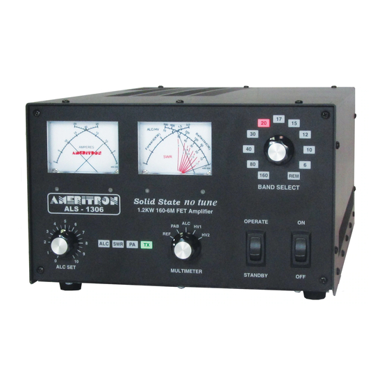
Front Panel Amplifier Front Figure 2 The front panel contains the following indicators and controls. To prevent damage, become familiar with the front panel before operating the amplifier. 1 FET module current meters 2 Forward Power meter and Multimeter (reflected power, module RF balance, ALC, and Module supply voltages) selected by knob 7. -
Page 18: Operation
25-28 MHz range is not available, irrespective of licensing or end-use. Warning Lights The ALS-1306 has three primary warning lights in the center of the front panel. It also uses other standard LED’s as warnings, flashing them in a certain code that indicates problems. These lights serve the following functions: ALC: The yellow ALC light indicates ALC output. -
Page 19: Initial Operation
Warning Warning light Fault Cause or Cure light Flash Steady Antenna Reflected High antenna SWR or Power intermittent antenna or feed line connection Wrong filter Exciter or amplifier on SWR, PA Band incompatible band, filter failure PA FET too hot Excessive power for duty cycle or SWR, lack of proper airflow Combiner unbalance... -
Page 20: Alc Adjustment
On SSB, it will show as a slow warble or modulation of power levels, especially at the very start of voice transmissions. If you observe ALC attack bounce, the ALS-1306 will require ALC gain adjustment. The ALS- 1306 has a small blade screwdriver adjustment for setting ALC gain. This adjustment on the left cabinet side behind the front panel, near the panel meters. -
Page 21: Als-1306 Functional Overview
ALS-1306 Functional Overview The ALS-1306 is an amateur radio multiband radio frequency linear power amplifier. This device complies with technical standards of CFR Title 47 part 97.317(a) and (b). General Operation This linear amplifier covers the 160, 80, 40, 30, 20, 17, 15, 12, 10, and 6-meter amateur bands. -
Page 22: 2Kwf6 Lowpass Filter Assembly
CB2 also contains bias, relay sequencing, and fan speed controls. The CB2 board contains band-decoding systems, and automatically disables operation between 25 and 28 MHz in all ALS-1306 amplifiers regardless of band selection mode. This embedded logic function cannot be disabled or changed. -
Page 23: Circuit Boards
Circuit Boards There are ten basic circuit boards plus two power amplifier modules in the ALS-1306. The text below gives a brief description of each board’s function. 2KWF6 The 2KWF6 is a high-power low-pass filter. It is the very large topmost board with several large toroids and air wound inductors. -
Page 24: Swr
The SWR board is on the rear panel in front of the RF output connector. It is a traditional 50- ohm directional coupler. The null adjustment is accessible through a rear panel hole. Revision 2... -
Page 25: Schematics
Schematics Filter 2KWF6 PA A PA B 2KWF6 Rev1.2 RADIO PA IN 7to1 250V 12-90pF Rly Board 220pF 1401 220pF Rly Board 0.001uF 1401 1.5k 0.01uF 30pF 30pF 30pF RL13 RL14 0.1uF RLY13 RLY14 RL11 RLY11 RLY12 RL12 0.1uF RL10 6.5T 6.5T 0.1uF... -
Page 26: Bandswitch Bsw3
Bandswitch BSW3 Band Switch BSW3 Rev0 **J1** .1uF 2 5V+ 3 RCK 4 SCK 5 SER Remote .001uF .001uF .1uF 10 A .001uF .1uF .1uF .1uF 74HC595 74HC148 SCLR LED9 LED10 2.2k 2.2k 2.2k LED7 LED8 LED11 2.2k 2.2k REMOTE LED6 LED5 2.2k... -
Page 27: Control Board Cb2
Control Board CB2 Sheet 1 Sheet 2 CB2 control board Figure 6 Revision 2... -
Page 28: Power Divider Pd8
Power Divider PD8 OUT B OUT A 4.7K 2W MOX PD8 Rev2.1 Out C -8db splitter PD8 Power Divider Figure 7 SWR Sensor Board SWR Sensor Figure 8 Revision 2... -
Page 29: Metering Board Mb2
Metering Board MB2 J2 Multimeter J1 Control PIN 1...GND PIN 1...GND 2...FWD 2...12 - 3...MM - -12V 3...12 + FWD HOLD REF HOLD 4...MM + 4...FWD PWR R16 1M 40% 5...LMP 5...RFLCTD PWR 1M 40% 6...GND 6...TRANSMIT LED 7...COMBINER LED 8...SWR LED 1N914 9...ALC VOLTAGE OUT... -
Page 30: Pa Module
PA Module Not used PA Module Rev1.2 1306 OY Omite 0.001uF 0.33uF Not used 0.33uF 0.1uF Not used 0.1uF OY Omite Not used 0.001uF Not used Not used 0.1uF Not used PA Out R27 22 50ohm 0.1uF R25 22 T T2 R23 22 300pF 300pF... -
Page 31: Reference Figures And Drawings
Reference figures and drawings Interconnections Figure 1 ......................14 Amplifier Front Figure 2....................... 17 2KWF6 output filter Figure 3 ....................... 25 BSW3 bandswitch figure 4 ......................26 RJ45 Interface Board Figure 5...................... 26 CB2 control board Figure 6 ......................27 PD8 Power Divider Figure 7...................... -
Page 32: Disclaimer
IMITED ARRANTY Ameritron warrants to the original purchaser that this product shall be free from defects in material or workmanship for one year from the date of original purchase. During the warranty period, Ameritron (or an authorized Ameritron service facility) will provide free of charge both parts and labor necessary to correct defects in material or workmanship.
Need help?
Do you have a question about the ALS-1306 and is the answer not in the manual?
Questions and answers