Table of Contents
Advertisement
Quick Links
Smart encoders & actuators
SMA1 +
MTA1
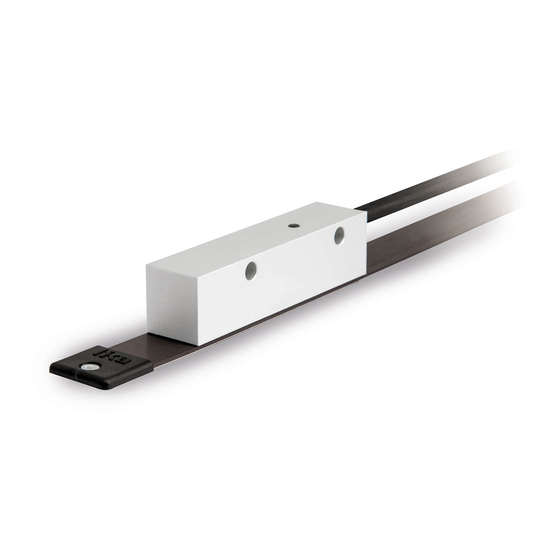
• SMA1 absolute linear encoder
• MTA1 tape, 1 mm pitch, unaffected by dust and liquids
• Max. measuring length 5,015 mm / 200.1"
• Resolution 5 µm
• SSI & BiSS interfaces + AB Sine/Cosine track for speed feedback
Suitable for the following models:
SMA1 -GA2-...
•
SMA1 -SB1-...
•
SMA1 -SB2-...
•
SMA1 -SC1-...
•
SMA1 -SC2-...
•
Lika Electronic
User's guide
•
Tel. +39 0445 806600
Table of Contents
•
info@lika.biz
10
11
14
16
20
31
42
43
•
www.lika.biz
8
9
Advertisement
Table of Contents

Subscribe to Our Youtube Channel
Related Manuals for Lika SMA1 Series


Summary of Contents for Lika SMA1 Series
-
Page 1: Table Of Contents
SMA1 -SC2-... • 5 - SSI interface 6 - BiSS B-mode interface 7 - BiSS C-mode interface 8 - 1Vpp sine/cosine output signals 9 - Error and fault diagnostics Lika Electronic • Tel. +39 0445 806600 • info@lika.biz • www.lika.biz... - Page 2 Tous droits réservés. This document and information contained herein are the property of Lika Electronic s.r.l. and shall not be reproduced in whole or in part without prior written approval of Lika Electronic s.r.l. Translation, reproduction and total or partial modification (photostat copies, film and microfilm included and any other means) are forbidden without written authorisation of Lika Electronic s.r.l.
-
Page 3: General Contents
General contents User's guide......................................1 General contents....................................3 Subject index......................................6 Typographic and iconographic conventions........................7 Preliminary information..................................8 1 - Safety summary............................9 1.1 Safety......................................9 1.2 Electrical safety..................................9 1.3 Mechanical safety................................10 2 - Identification............................10 3 - Mounting instructions......................... 11 3.1 Overall dimensions................................11 3.2 Magnetic scale..................................11 3.3 Mounting the sensor.................................12 4 - Electrical connections........................... - Page 4 Configuration................................25 Select BiSS / SSI...............................25 Set preset / offset..............................25 Enable preset / offset............................25 Output code................................26 Counting direction..............................26 Absolute resolution..............................26 Preset / Offset................................27 Device type..................................28 SINE / COSINE resolution...........................28 Device ID..................................28 Manufacturer ID..............................29 6.6 Application note..................................29 6.7 Examples....................................29 6.7.1 Setting the Configuration register........................29 6.7.2 Setting the Preset / Offset register........................30 6.8 Recommended BiSS circuit.............................30 7 - BiSS C-mode interface.........................
- Page 5 7.7 Examples....................................40 7.7.1 Setting the Configuration register........................40 7.7.2 Setting the Preset / Offset register........................41 7.8 Recommended BiSS circuit.............................41 8 - 1Vpp sine/cosine output signals......................42 8.1 Output signals voltage level............................42 9 - Error and fault diagnostics........................43 9.1 Diagnostic LED..................................43 10 - Maintenance............................
-
Page 6: Subject Index
Subject index Absolute resolution..........26, 37 Normal operation.............24, 35 Command..............24, 35 Offset................27, 38 Configuration.............25, 36 Output code..............26, 37 Counting direction...........26, 37 Preset................27, 38 Device ID..............28, 39 Preset / Offset............27, 38 Device type..............28, 39 Profile ID...............23, 35 Enable preset / offset..........25, 36 Save and activate Preset / Offset......24, 35 Save parameters on EEPROM......24, 35 Select BiSS / SSI..............25... -
Page 7: Typographic And Iconographic Conventions
Typographic and iconographic conventions In this guide, to make it easier to understand and read the text the following typographic and iconographic conventions are used: parameters and objects both of the device and the interface are coloured in GREEN; • alarms are coloured in RED;... -
Page 8: Preliminary Information
This guide is designed to provide the most complete and exhaustive information the operator needs to correctly and safely install and operate the SMA1 series absolute linear encoder. SMA1 is designed to measure displacements in industrial machines and automation systems. The measurement system includes a magnetic tape and a magnetic sensor with conversion electronics. -
Page 9: Safety Summary
• elsewhere in this manual violates safety standards of design, manufacture, and intended use of the equipment; Lika Electronic assumes no liability for the customer's failure to comply • with these requirements. 1.2 Electrical safety Turn OFF the power supply before connecting the device;... -
Page 10: Identification
Information is listed in the delivery document too. Please always quote the order code and the serial number when reaching Lika Electronic for purchasing spare parts or needing assistance. For any information on the technical characteristics of the product refer to the technical datasheet. -
Page 11: Mounting Instructions
SMA1 3 - Mounting instructions WARNING Installation has to be carried out by qualified personnel only, with power supply disconnected and mechanical parts compulsorily in stop. 3.1 Overall dimensions 3.2 Magnetic scale The sensor has to be paired with the MTA1 type magnetic scale only. For detailed information on the MTA1 type scale and how to mount it refer to the specific technical documentation. -
Page 12: Mounting The Sensor
SMA1 3.3 Mounting the sensor Figure 1 Make sure the mechanical installation complies with the system requirements concerning distance, planarity and parallelism between the sensor and the scale. Avoid contact between the parts. Sensor is fixed by means of two M5 25 mm min. - Page 13 SMA1 Figure 2 WARNING After having installed the sensor on the magnetic scale a zero setting operation is compulsorily required. The zero setting operation is further required every time either the sensor or the scale is replaced. Refer to pages 27 and 38. Not available for SSI interface.
-
Page 14: Electrical Connections
+Vdc = +10Vdc +30Vdc → SMA1-SB1-... +Vdc = +5Vdc ±5% 4.1 T12 cable specifications Model : LIKA T12 cable Wires : 4 x 0.25 mm + 4 x 2 x 0.14 mm twisted pairs Shield : tinned copper braid External diameter : Ø... -
Page 15: M12 12-Pin Connector
SMA1 4.2 M12 12-pin connector M12 12-pin connector A coding Male frontal side 4.3 Ground connection Minimize noise by connecting the cable shield and/or the connector housing and/or the sensor to ground. Make sure that ground is not affected by noise. The connection point to ground can be situated both on the device side and on user’s side. -
Page 16: Ssi Interface
SMA1 5 - SSI interface Order code: SMA1-GA2-5-… 5.1 SSI (Synchronous Serial Interface) Synchronous Serial SSI (the acronym Interface) is a synchronous point-to-point serial interface engineered unidirectional data transmission between one Master and one Slave. Developed in the first eighties, it is based on the RS- 422 serial standard. -
Page 17: Lsb Right Aligned Protocol
SMA1 means that up to n + 1 rising edges of the clock signals are required for each data word transmission (where n is the bit resolution); for instance, a 13-bit encoder needs 14 clock edges. If the number of clocks is greater than the number of bits of the data word, then the system will send a zero (low logic level signal) at each additional clock, zeros will either lead (LSB ALIGNED protocol) or follow (MSB ALIGNED protocol) or lead and/or follow (TREE FORMAT... -
Page 18: Recommended Transmission Rates
SMA1 5.3 Recommended transmission rates The SSI interface has a frequency of data transmission ranging between 100 kHz and 1 MHz. The CLOCK signal and DATA signal comply with the “EIA standard RS-422”. The clock frequency (baud rate) depends on the length of the cable and must comply with the technical information reported in the following table: Cable length Baud rate... -
Page 19: Recommended Ssi Circuit
SMA1 5.5 Recommended SSI circuit MAN SMA1 E 2.9.odt 5 - SSI interface 19 of 48... -
Page 20: Biss B-Mode Interface
Never connect the sensor in a “single Master - Multi Slave” network. CLOCK MA and DATA SLO signal levels comply with the “EIA standard RS-422”. 6.1 XML file The product is supplied with an XML file idbiss4C69.xml (see at www.lika.biz). Install the XML file in your BiSS Master device. 6.2 Communication... -
Page 21: Data
SMA1 DATA (8 bits) When writing to the register: this is the value to be set in the register (i.e. transmitted from the Master to the Slave). When reading from the register: this is the value read in the register (i.e. transmitted from the Slave to the Master). -
Page 22: Position
SMA1 Position (24 bits) Process data to be transmitted from the Slave to the Master. The transmission starts with the MSB (most significant bit) and ends with the LSB (least significant bit). 31 … 28 … value 0000 … To convert the position value into mm, multiply the received data value by the resolution (see 4Dhex Absolute resolution register). -
Page 23: Used Registers
SMA1 Logic circuit: stage stage stage stage stage stage Input Data (starts from MSB) 6.5 Used registers Register (hex) Function 42 - 43 Profile ID 44 … 47 Serial number Command Configuration Absolute resolution 51 … 53 Preset / Offset Device type SINE / COSINE resolution 78 …... -
Page 24: Command
Load and save default parameters: default parameters are set at the factory by Lika Electronic engineers to allow the operator to run the device for standard operation in a safe mode. As soon as the command is sent the default parameters are uploaded and activated. -
Page 25: Configuration
SMA1 Configuration [49, rw] Function Bit = 0 Bit = 1 Select BiSS / SSI BiSS Set preset / offset Preset Offset Enable preset / offset Enable Disable Not used Not used Output code Binary Gray Counting direction * Standard Inverted Not used *: it affects the absolute position information, not the sine/cosine signals Select BiSS / SSI... -
Page 26: Output Code
SMA1 Output code The sensor provides the absolute position information in the desired code format: GRAY (0) or BINARY (1). Default = 1 (Binary) Counting direction The standard counting direction is to be intended with sensor moving as indicated by the arrow in Figure 1. This parameter allows to reverse the counting direction. -
Page 27: Preset / Offset
SMA1 Preset / Offset register and activate it by sending the command Save and activate Preset / Offset (set “02” in the register 48). Default = 05h. Preset / Offset [51 … 53, rw] This function is available only if the Enable preset / offset parameter in the Configuration register is set to ENABLE. -
Page 28: Device Type
SMA1 Preset / Offset structure: Reg. … Use the Save and activate Preset / Offset function (set “02” in the register 48) to store and activate the new value. The max. allowed Preset value depends on the set resolution: resolution = 0.1 ... -
Page 29: Manufacturer Id
Manufacturer ID [7E - 7F, ro] These registers show the Manufacturer ID, hexadecimal values are according to ASCII code. Reg. ASCII Li = Lika Electronic. 6.6 Application note Device communication specifications: Parameter Clock Frequency Sensor Mode 350 kHz 10 MHz... -
Page 30: Setting The Preset / Offset Register
SMA1 6.7.2 Setting the Preset / Offset register After having enabled and chosen the PRESET function (Enable preset / offset = ENABLE; Set preset / offset = PRESET in the Configuration register, see the previous “6.7.1 Setting the Configuration register“ section), you want to set and activate the new Preset value = 100000 = 01 86 A0h Function... -
Page 31: Biss C-Mode Interface
Never connect the sensor in a “single Master - Multi Slave” network. CLOCK MA and DATA SLO signal levels comply with the “RS-422 EIA standard”. 7.1 XML file The product is supplied with an XML file idbiss4C69.xml (see at www.lika.biz). Install the XML file in your BiSS Master device. 7.2 Communication The BiSS C-mode protocol uses two types of data transmission protocols: Single Cycle Data (SCD): this is the primary data transmission protocol. -
Page 32: Single Cycle Data
SMA1 7.3 Single Cycle Data SCD (32 bits) consists of the following values: 24-bit position value (Position), 1 error bit (Error, nE), 1 warning bit (Warning, nW) and CRC checking (CRC, 6 bits). SCD structure: bits 31…8 5…0 function Position Error Warning Position... -
Page 33: Crc
SMA1 (6 bits) CRC, namely Cyclic Redundancy Check, is the error checking field resulting from a “Redundancy Check” calculation performed on the message contents. This is intended to check whether transmission has been performed properly (inverted output). Polynomial: X +1 (binary: 1000011) Logic circuit: stage stage... -
Page 34: Crc
SMA1 Data bit structure: … … … … (4 bits) CRC, namely Cyclic Redundancy Check, is the error checking field resulting from a “Redundancy Check” calculation performed on the message contents. This is intended to check whether transmission has been performed properly (inverted output). -
Page 35: Profile Id
Load and save default parameters: default parameters are set at the factory by Lika Electronic engineers to allow the operator to run the device for standard operation in a safe mode. As soon as the command is sent the default parameters are uploaded and activated. -
Page 36: Configuration
SMA1 WARNING As soon as the Load and save default parameters command is sent, all parameters which have been set previously are overwritten, thus previously set values are lost! As soon as the command is sent, the register is set back to "00" (Normal operation) automatically. -
Page 37: Output Code
SMA1 the Set preset / offset parameter. Then to activate a new value, set it next to Preset / Offset register and send the Save and activate Preset / Offset command (set “02” in the register 48). Default = 0 (enable) Output code The sensor provides the absolute position information in the desired code format: GRAY (0) or BINARY (1). -
Page 38: Preset / Offset
SMA1 The new setting will be active immediately after transmission. Use the Save parameters on EEPROM function (set “01” in the register 48) to store the new value. NOTE If the preset / offset functions are active, after having set a new value next to Absolute resolution this register, then you must check the value in the... -
Page 39: Device Type
SMA1 Offset register and then send the Save and activate Preset / Offset command Command in the register (set “02” in the register 48). Preset / Offset structure: Reg. … Use the Save and activate Preset / Offset function (set “02” in the register 48) to store and activate the new value. -
Page 40: Manufacturer Id
Manufacturer ID [7E – 7F, ro] These registers show the Manufacturer ID, hexadecimal values are according to ASCII code. Reg. ASCII Li = Lika Electronic. 7.6 Application note Device communication specifications: Parameter Value Clock Frequency min 200 kHz, max 10 MHz... -
Page 41: Setting The Preset / Offset Register
SMA1 7.7.2 Setting the Preset / Offset register After having enabled and chosen the PRESET function (Enable preset / offset = ENABLE; Set preset / offset = PRESET in the Configuration register, see the previous “7.7.1 Setting the Configuration register“ section), you want to set and activate the new Preset value = 100000 = 01 86 A0h Function... -
Page 42: 1Vpp Sine/Cosine Output Signals
SMA1 8 - 1Vpp sine/cosine output signals The frequency of sine/cosine output signals is proportional to the displacement speed of the sensor. A (COSINE) and B (SINE) signals (standard counting direction, see Figure 1) P is the electrical period length. P = 1 mm, i.e. -
Page 43: Error And Fault Diagnostics
SMA1 9 - Error and fault diagnostics In case of wrong alignment between the sensor and the magnetic scale, at power on or during operation the following errors may occur: the LED lights up when switching on the system: there is a wrong alignment;... -
Page 44: Maintenance
SMA1 10 - Maintenance The magnetic measurement system does not need any particular maintenance; anyway it has to be handled with the utmost care as any delicate electronic equipment. From time to time we recommend the following operations: periodically check the soundness of the structure and make sure that there are no loose screws;... -
Page 45: Troubleshooting
SMA1 11 - Troubleshooting The following list shows some typical faults that may occur during installation and operation of the magnetic measurement system. Fault The system does not work (no pulse output). Possible cause The scale and/or the sensor are not installed properly (the active surface of the scale does not match the sensitive part of the sensor). -
Page 46: Default Parameters List
SMA1 12 - Default parameters list BiSS B-mode interface Parameters list Default value * Command Configuration Bit 0 Select BiSS / SSI 0 = BiSS Bit 1 Set preset / offset 0 = Preset Bit 2 Enable preset / offset 0 = Enable Bit 3 not used Bit 4 not used... - Page 47 This page intentionally left blank...
- Page 48 “3 - Mounting instructions“ section update 20.04.2016 General review, new BiSS order codes 11.05.2016 M12 12-pin connector added 05.05.2020 Sine-Cosine track extended to SSI interface Lika Electronic Via S. Lorenzo, 25 • 36010 Carrè (VI) • Italy Tel. +39 0445 806600 Fax +39 0445 806699 info@lika.biz...
Need help?
Do you have a question about the SMA1 Series and is the answer not in the manual?
Questions and answers