
Subscribe to Our Youtube Channel
Related Manuals for ITR Hurricane Zephyr HW


Summary of Contents for ITR Hurricane Zephyr HW
- Page 1 Installation and Operating Manual ® ™ Hurricane Zephyr Diesel Heating System for Yachts International Thermal Research...
- Page 2 International Thermal Research Right to Modify: Due to our commitment for quality and ongoing product improvement, ITR reserves the right to modify or change without notice, any materials, applications, equipment, accessories, and/or prices. All measurements and weights are approximate.
-
Page 3: Table Of Contents
Table of Contents Table of Contents Technical Specifications and Standards Dangers • Warnings • Cautions • Notices Section 1, Overview..............1-1 Unpacking the Heating System......... 1-2 Protect Your Warranty ............ 1-2 Heater Features............. 1-3 Critical Factors .............. 1-5 Equipment, Tools, and Skills ..........1-5 Testing and Inspection............ - Page 4 Table of Contents Section 6, Wiring the Electrical System........6-1 Before You Begin............6-1 Hurricane® Zephyr™ 12 VDC........... 6-1 Hurricane® Zephyr™ 120/240 VAC (Optional) ....6-2 Procedure ..............6.3 Electrical Components............. 6-3 What NOT to DO ............6-6 Procedure ..............6-6 Electrical Schematic............
- Page 5 Table of Contents 10.3 Burner On ..............10-1 10.4 Service Switch Off............10-2 10.5 Remote Switch Off ............10-2 10.6 Heater Cycling .............10-2 10.7 Thermostats Off............10-3 10.8 Voltage Low of High ............10-3 10.9 Overheat ..............10-4 10.10 Fuse Blown ..............10-4 10.11 Fuel Pump/Solenoid ............10-5 10.12 Ignitor ................10-5 10.13...
- Page 6 Table of Contents List of Figures Figure 1-1 Hurricane® Zephyr™ HW Heating System ..... 1-1 Figure 1-2 Hurricane® Zephyr™ HW Heating System Overview ..1-4 Figure 1-3 Hurricane® Zephyr™ HW Typical seiries-Plumbed Layout . 1-7 Figure 2-1 Hurricane® Zephyr™ HW Dimensions ......2-3 Figure 2-2 Heater Mounting bracket configuration ......
-
Page 7: Section 1, Overview
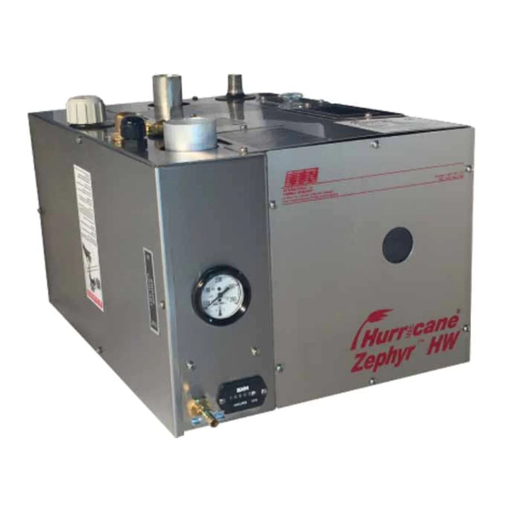
If in doubt, contact ITR for assistance. Figure 1-1: Hurricane® Zephyr™ HW Heating System International Thermal Research... -
Page 8: Unpacking The Heating System
ITR equipment. The heater and supplied components are only guaranteed by ITR if the entire system has been installed according to the requirements and recommendations set forth in this manual. Warranty coverage will not be extended to heaters and... -
Page 9: Heater Features
Section 1, Overview Heater Features ™ is an advanced and efficient Hurricane® Zephyr hydronic heater with many advantages over older technology of forced-air systems. The Zephyr™ provides space heating using a “heat-transfer fluid” pumped to remote mounted, fan Hurricane® Zephyr™ equipped, radiator-style heat-exchangers. - Page 10 Section 1, Overview · Electronically-controlled system with: o Automatic safety shutdown o Manual reset overheat temperature sensor and a thermal cutoff for overheat protection o Tactile, Touch screen control panel for operating control and diagnostics with audible alarm · Heating control for up to four separate space heating zones, each with its own optional thermostat ·...
-
Page 11: Critical Factors
Ability to easily access and service the product, especially fuel, plumbing, and electrical systems · After installation, ability to purge water and fuel lines and inspect/test entire system using the ITR-supplied Inspection Check Sheet. Equipment, Tools, and Skills As the user and/or installer, you must be qualified and authorized to do the installation, which requires mechanical aptitude and electrical knowledge. -
Page 12: Testing And Inspection
Section 1, Overview · ¼” ID approved fuel supply and return lines · #10 sheet metal screws or wood screws for mounting internal fans. · Heater hose – enough to connect the Hurricane Zephyr to the interior fans. If engine heat is used, heater hose is required to connect the heater to the engine block (see Technical Specifications and Standards for details) ·... - Page 13 Section 1, Overview ™ Figure 1-3: Hurricane® Zephyr HW Typical Series-Plumbed Layout International Thermal Research...
- Page 14 Section 1, Overview Hurricane Installation Manual for ® Zephyr™ HW Heating System...
-
Page 15: Before You Begin
Section Mounting – Hurricane ® Zephyr Heating System Before You Begin ® Plan the location of the Hurricane Zephyr Heating System and all its major components in advance to ensure the chosen locations are compatible with installation requirements and within the technical specifications. -
Page 16: Mounting Location
Section 2, Mounting the Heater Unit Mounting Location · Mounting location must be able to support double the gross weight of the heater when full (i.e.70 lbs. x 2 = 140 lbs./63.5 KG) and must be of a non-combustible material. ®... -
Page 17: Figure 2-1 Hurricane® Zephyr™ Hw Dimensions
Section 2, Mounting the Heater Unit Figure 2-1: Hurricane® Zephyr™ HW Dimensions If the Hurricane® Zephyr™ HW is going to be mounted in the WARNING engine compartment, check for adequate ventilation. Make sure there are no exhaust leaks and that all exhaust fittings are well- fastened to the heater and the muffler. -
Page 18: What Not To Do
Section 2, Mounting the Heater Unit 2.3 What NOT TO DO Don’t mount the heater without a direct connection to the combustion fan from an outside air source. Don’t mount the heater without exhaust fittings installed and the exhaust directed outside the boat. Don’t mount the heater in a location that restricts access to the service panels or creates interference with the top mounted connections. -
Page 19: Remote Operating Touch Screen Panel Mounting Procedure
Section 2, Mounting the Heater Unit Remote Operating Touch Screen Panel Mounting Procedure The Remote Operating Panel is mounted inside the Yacht, in an easy to access location. An opening for the remote panel must be cut in the wall or mounting panel. The Remote Operating Panel will be screwed in place using the 4 mounting holes. - Page 20 Section 2, Mounting the Heater Unit Hurricane Installation Manual for ® Zephyr™ HW Heating...
-
Page 21: Section 3, Installing The Exhaust System
For efficient and safe operation of the Hurricane® Zephyr™ HW follow all recommendations for properly installing the exhaust. Any deviations from these recommendations must be approved in advance by ITR. Although the heater’s exhaust produces very low carbon monoxide ! DANGER emissions, caution is advised: ·... - Page 22 · Combustion air must be drawn directly from outside the yacht using a two inch air intake hose connected to the ITR 1.5" OD dual thru hull fitting, an ITR air intake fitting, or by placing the air intake hose near a fresh outside air vent.
-
Page 23: What Not To Do
Don’t disregard the total number of 90° bends when calculating the total allowable exhaust length (12’ total, excluding the 90° bend exiting the heater) Don’t use any mufflers not supplied or approved by ITR. Installation Procedure To install the exhaust system: Refer to Figure 3-1: Hurricane Zephyr™... - Page 24 Section 3, Installing the Exhaust System 5Find a suitable location to mount the air-intake silencer (part# 10455) if you are using one . 6Connect the flexible air-intake tubing (2” ID part# 8019) to the air-intake fitting on top of the heater. The other end of the air-intake hose can be installed on the dual through hull or near an air intake vent in the yacht.
-
Page 25: Section 4, Installing The Fuel System
For efficient and safe operation of the Hurricane® Zephyr™ HW, follow all recommendations for properly installing the fuel system. Any deviations from these must be approved in advance by ITR. Although the Hurricane® Zephyr™ HW will work with furnace oil, stove oil, and jet fuel, it is only certified to be used with diesel #1 and #2. -
Page 26: What Not To Do
Section 4, Installing the Fuel System lines from the boat's fuel supply are push fit onto the male end of the quick connect fittings. The fuel return line should return directly to the fuel supply tank. The following is recommended for the fuel system installation: The fuel supply from the fuel storage tank to the fuel inlet must be NOTICE from a dedicated fuel pickup on the top of the tank. -
Page 27: Procedure
Section 4, Installing the Fuel System Procedure To complete the fuel system installation: Install the inline fuel filter. The optimal location is on a compartment wall next to the Hurricane® Zephyr™ HW, inline between the fuel tank and the heater. Connect the fuel supply line to a dedicated pick-up fitting on the main diesel fuel tank. - Page 28 Section 4, Installing the Fuel System Installation Manual for Hurricane® Zephyr™ HW Heating System...
-
Page 29: Section 5, Installing Fan Heaters
Section Installing Fan Heaters Before You Begin ITR makes a variety of 12 VDC fans for heating separate or combined areas: Small Space Cabin Fan (6095) - 0.5 Amp., 4000 BTU/h. Low-Profile Cabin Fan (6132) - 1 Amp., 6000 BTU/h. -
Page 30: Fan System Operation
Section 5, Installing Fan Heaters 5.2 Fan System Operation ITR fans consist of a 12 VDC brushless fan and heater coil similar to a radiator. When the heating fan comes on, the fan draws ambient air from the interior, blows it across the heater coil and back into the interior through a vent. -
Page 31: Accessories And Components Needed
Switches — to enable low, medium and high-speed settings from inside the yacht; for use with the ITR defrost heater. · Air Ducting — to allow for installation of fans in a remote location (i.e. not directly adjacent to the space to be heated) and duct the heated air to its needed location. -
Page 32: Mounting Locations
ITR’s cabin heater fans come with loose or built in brackets. The fan can be mounted on the floor or on the wall, either flat or on its side. -
Page 33: Figure 5-3 Installing A Relay For Additional Fan Amperage
Section 5, Installing Fan Heaters Figure 5-2: Mounting a Low-Profile Cabin Fan Figure 5-3: Installing a Relay for Additional Fan Amperage International Thermal Research... - Page 34 Section 5, Installing Fan Heaters Installation Manual for Hurricane® Zephyr™ HW Heating System...
-
Page 35: Section 6, Wiring The Electrical System
Section Wiring the Electrical System Before You Begin The heater and its electrical control board are pre-wired and have been thoroughly tested together as a unit. To review the wiring system for the entire heating system, refer to the schematic at the end of this section (Figure 6-4.) All electrical connections and wiring must comply with ! WARNING normally-accepted 12 VDC and 120 VAC wiring practices, local... -
Page 36: Hurricane® Zephyr™ 120/240 Vac (Optional)
Section 6, Wiring the Electrical System · The 12 VDC connections to the Hurricane® Zephyr™ control board must be connected directly to the battery (through a fuse). There should be no battery disconnect switch between battery Hurricane® Zephyr™ control board. This is to prevent the burner from being shut down without first going through its appropriate purge period. -
Page 37: Procedure
Section 6, Wiring the Electrical System Figure 6-1: Sample Wiring Diagram for Electrical Elements Procedure To use only the electric heating element: Turn ON, the switch shown in Figure 6-1. This will turn on the electric heating element and will heat the coolant inside of the tank. - Page 38 Section 6, Wiring the Electrical System · Fuses – The control board contains four fuse holders with fuses pre-installed. These standard, automotive, spade type fuses available from most auto parts stores. · Thermal Cutoff - The heater burner box contains a non-resettable thermal cut-off...
- Page 39 Section 6, Wiring the Electrical System · Circulating pump jumper – on the control board allows the circulating pump to operate without turning on the heater. This function is use to test the system circulation. · Battery connector – is the connection points for the positive and negative power from the house battery to the heater.
-
Page 40: What Not To Do
Section 6, Wiring the Electrical System What NOT TO DO Never shut off power to the heater via an inline battery or master switch while the system is running. Never disconnect NOTICE the battery when the heater is running, and never disconnect the battery while the inverter is charging. - Page 41 Section 6, Wiring the Electrical System Wire the positive terminal of the house battery through a 25-amp, heavy-duty rated fuse (using #10-gauge wire) to the positive terminal on the control board inside the main control box. Wire the negative terminal of the house battery to the negative terminal of the control board.
-
Page 42: Figure 6-2 Wiring For A Fan Speed Switch
Section 6, Wiring the Electrical System Figure 6-2: Wiring for a Fan Speed Switch Installation Manual for Hurricane® Zephyr™ HW Heating System... - Page 43 Section 6, Wiring the Electrical System International Thermal Research...
-
Page 44: Section 7, Plumbing And Filling The System
For efficient and safe operation of the Hurricane Zephyr Heating System, follow all of the recommendations in this section for proper installation of the plumbing system. Any deviations from these must be approved in advance by ITR. ® The Hurricane Zephyr Heating System must use a non-toxic,... -
Page 45: Heat Transfer Fluid/Plumbing Installation Procedure
All connections must be tested to be leak free. ITR warranty does not cover damage caused by leaks from connections made during installation. - Page 46 Section 7, Plumbing the System Do not operate the Hurricane® Zephyr Heating System until a proper DANGER anti-freeze (heat transfer fluid) solution has been added to the heating system and all trapped air has been bled. An inadequate mixture may cause system circulation problems and potential heating system damage and/or personal injury.
-
Page 47: What Not To Do
Section 7, Plumbing the System ® Figure 7-2: Plumbing Hurricane Zephyr for 3 Zones with (optional) summer loop What NOT TO DO ® The Hurricane Zephyr Heating System’s coolant distribution pump NOTICE is one of the most critical parts of the system. Never let the pump run dry or damage will occur to the rotor. -
Page 48: Potable Water Plumbing Installation
120F (49°C). If needed this valve can be adjusted between a range of 75F (24°C) to a maximum of 145F (63°C). See Figure 7-4: Potable Hot water system plumbing. ITR warranty does not cover damage caused by leaks from NOTICE connections made during installation. -
Page 49: Engine Waste-Heat And Engine Pre-Heat Plumbing
Section 7, Plumbing the System Figure 7-4 Potable Hot Water System Plumbing Engine Waste-heat and Engine pre- heat Plumbing Refer to figure 7-5: Engine heat/pre-heat system plumbing. ® Hot coolant from the engine enters the Hurricane Zephyr at the connection labeled “Engine Supply” and returns to the engine from ®... -
Page 50: Figure 7-5 Engine Heat / Pre-Heat System Plumbing
Section 7, Plumbing the System Prior to operating the engine pre-heat pump, the engine coolant loop WARNING ® must be connected to the Hurricane Zephyr and the coolant lines purged of air. Failure to purge the engine coolant loop prior to operating the circulation pump, will damage the pump. -
Page 51: Figure 7-6 Filling/Purging Hurricane Zephyr Heating System
Section 7, Plumbing the System ® Remove the front cover of the Hurricane Zephyr, also remove the cover of the control board to provide access to the circulation pump jumper on the circuit board See diagram below. Using a self-priming pump, fill the system through the filler port (1/2"... -
Page 52: Before You Begin
Section Domestic Hot Water Heating Engine Heat Management Before You Begin When the heater is used only for heating domestic water and space heating is not required, a three-way valve or electric solenoid can be installed. This valve is intended to divert the heat transfer fluid through the heat exchanger but not the space heating loop Refer to Fig. -
Page 53: Engine Waste Heat Function
Section 8, Domestic Hot Water Heating Domestic water sensing switch — If desired, you can install a manual switch to turn the domestic hot water sensing circuit on and off. This switch is connected to the W1 and W2 terminals on the accessory terminal block. -
Page 54: Procedure
Section 8, Domestic Hot Water Heating It is not recommended to mix your engine cooling system NOTICE with your heating system. Before connecting anything to your engine, consult your engine owner’s manual for any restrictions or plumbing into the engine cooling system. Procedure To set up the engine waste heat reuse function: Turn OFF, the ON/OFF control switch, located on the... -
Page 55: Procedure
Section 8, Domestic Hot Water Heating Procedure To set up the engine pre-heat function: Mount a manual switch in an appropriate place in the interior, usually near the dashboard. Wire the manual switch to the engine water pump by connecting it to the main feed on the control board that connects to the boat’s power source (beside the battery connection, see Figure 6-4 in Section 6, Wiring the Electrical System). -
Page 56: Section 9, Operating The Hurricane Zepyhr Heating System
Section Operating the Hurricane Zephyr heating System This section describes the features, operation and maintenance of your new Hurricane® Zephyr™ HW Heating System. READ THESE INSTRUCTIONS AND SAVE FOR REFERENCE. 9.1 Features of the Hurricane® Zephyr Heating System The Hurricane® Zephyr Heating System uses an 33,000 BTU (true output) diesel burner controlled by a 12 VDC, multi-functional electronic controller as the primary source of heating a heat transfer fluid (anti-freeze and water). - Page 57 Section 9, Operation burner). An integral, adjustable water tempering valve (factory pre- set), will limit the temperature to 120F. • Easy to install and field serviceable with hookups and connections easily accessible from the top of the heater. Engine coolant connections are made from the back of the heater.
-
Page 58: Starting The Heater
Section 9 – Operation 9.2 Starting the Heater Never attempt start heater ! DANGER without the burner faceplate securely fastened to the burner box ® Do not operate the Hurricane Zephyr Heating System until it ! WARNING is filled with a suitable heat-transfer (water/anti-freeze) solution and all trapped air has been bled or removed. -
Page 59: Main Control Board Operation
Section 9, Operation all the zone thermostats are satisfied, or until the heater reaches its normal cycling temperature of approximately 180°F. Once the cycling temperature is reached, the burner will cycle off and the combustion fan will operate for an additional two minutes to purge the system. -
Page 60: Using The Electric Heating Elements
Section 9 – Operation To turn the Heater OFF, touch the OFF button on the Touchscreen remote control panel. Turn OFF the ON/OFF service switch on the main control board box. The heater will automatically run through the purge cycle, which takes about two minutes. The heater will not start again even if there is a call for heat from a thermostat or domestic water. -
Page 61: Domestic Water Temperature Adjustment
Section 9, Operation Domestic Water Temperature Adjustment A thermostatic mixing valve located under the top access panel ® on the Hurricane Zephyr allows temperature adjustment of the potable hot water. This mixing valve is factory set to limit the maximum water temperature to 120ºF (49°C) with a hot water demand (flow-rate) of 1.0 GPM or less, and an incoming water temperature of 60ºF (15ºC) or higher. -
Page 62: Stopping The Heater (Maintenance)
Section 9 – Operation The parts inside the heater are HOT when in operation. Use WARNING gloves when adjusting the mixing valve. Turning the mixing valve knob clockwise will decrease the hot water outlet temperature and turning the knob counter- clockwise will increase the temperature. - Page 63 Section 9, Operation Noise sources: · Loose connections · Switches and relay contacts operating inductive loads, such as motors, coils, solenoids, and relays etc. · All welding machinery · Heavy current carrying conductors · Fluorescent and neon lights The sensor input and power output lines, as well as the power source line, all have the potential to couple or link the control circuit to a noise source.
-
Page 64: Maintenance
Only personnel familiar with the equipment and its operation should perform the service tune-up. It is recommended that a certified dealer be contacted for this service; if a local dealer is not available contact ITR for information on service resources. ·... -
Page 65: Protecting The Heating System
Section 9, Operation fuel block must then be removed from its mounting position. Finally, the burner and combustion tube must be taken out by removing the nuts holding the burner box and tube in position. · If the tube is satisfactory, a thorough cleaning of the tube and burner chamber should be performed by blowing out and vacuuming any ash and carbon buildup. -
Page 66: Section 10, Troubleshooting
Section Troubleshooting 10.1 Overview electronic board consists flash microcontroller programmed to monitor the timing and safety functions of the heater. Each time the board is energized by a call for heat, it will check its own circuits for any problems. Should a problem exist, the board will shut down. -
Page 67: Service Switch Off
Section 10-Troubleshooting 10.4 – Service Switch Off The service switch is switched OFF. · The burner will shut down if it has been running. · The diagnostic code will be displayed. · The control board will purge the system with the combustion fan and circulating pump for two minutes. -
Page 68: Thermostats Off
Section 10. Troubleshooting run until the last thermostat is satisfied, then purge for two minutes and stop. · To maintain the system temperature the operating aquastat will cycle the burner off at 170° F (77°C) and on again at 149°F (65°C). -
Page 69: Overheat
Section 10-Troubleshooting 10.9 - Overheat The high temperature limit has been reached. · The burner will shut down. · The diagnostic code, 1 will be displayed. · The buzzer will sound for 10 seconds. · The control board will purge the system with the combustion fan and circulating pump for two minutes while it is checking if the overheat condition exists. -
Page 70: Fuel Pump/Solenoid
Section 10. Troubleshooting 10.11 - Fuel Pump/Solenoid The fuel pump or fuel solenoid has shorted. · The burner will shut down. · The diagnostic code, will be displayed. · The buzzer will sound for 10 seconds. · The control board will purge the system with the combustion fan and circulating pump for two minutes. -
Page 71: Combustion Fan
Section 10-Troubleshooting 10.13 Combustion Fan · The combustion fan or shorted. · The burner will shut down. · The diagnostic code will be displayed. · The buzzer will sound for 10 seconds. · The control board will purge with the circulating pump for two minutes. - Page 72 Section 10. Troubleshooting The single most common reason for flame out faults is when air enters the fuel system. This is normally caused by low fuel levels or loose fittings. As air accumulates and passes through the nozzle, it interrupts the fuel supply and shuts down the burner. When this happens, it may be necessary to reset the fault a few times to ensure all air has passed through the system.
-
Page 73: Compressor
Section 10-Troubleshooting · If the conditions that caused the flame fault have been addressed and the heater does not ignite, the thermal cutoff may have been activated by an overheat condition within the burner box. Using a multimeter, check for continuity across the leads of the thermal cutoff. -
Page 74: Water Pump On
10.20 Test Points The test points on the electrical control board allow for testing and troubleshooting of the ITR heater’s electrical system. You will need a voltage meter to plug into the test points Test Component Results / Optimal Condition... -
Page 75: Reduced Output
Section 10-Troubleshooting Test Component Results / Optimal Condition Point 8v Power The voltage should be between 7.9 and 8 volts. A lower voltage indicates Supply a problem with the voltage supply to the logic of the control board. Power to This is the battery voltage supplied to the control board;... -
Page 76: A Silent Killer
Section 10. Troubleshooting usually caused by the wrong fuel to air mixture. This can be affected by the following: Low voltage High altitude Dirty compressor air filter Low compressor air output Restricted combustion air flow (intake hose / exhaust hose / combustion chamber) Low combustion fan output (defective motor / wrong rotation / dirty fan blade) - Page 77 Section 10-Troubleshooting A normal exhaust system is under constant attack from salt corrosion, gases, vibration, and impacts. It is important to inspect the exhaust system on a routine basis. Start with a visual inspection for signs of damage and check each joint for discoloration from exhaust gas leaks, or other signs that may indicate a possible leak.
-
Page 78: Section 11, Maintenance
Section Maintenance 11.1 The First Few Weeks Once the Hurricane® Zephyr™ HW heater has been installed to approved standards and workmanship, and you have test operated it a few times, the system will require little maintenance. About two weeks after your Hurricane® Zephyr™ HW heater has been running, you should conduct a general inspection of the entire system. -
Page 79: Nozzle
Section 11, Maintenance We recommend that you add a mixture of 50% water and 50% antifreeze. NEVER use more than a 50/50 mixture, since the added viscosity of the antifreeze solution will cause circulation problems. Your antifreeze/water mixture should be changed every three years. -
Page 80: Electrical System
Section 11, Maintenance fitting. Hoses, air lines and fuel lines will deteriorate over time and may crack. Replace any sections of worn hose together with the clamp. 11.7 Electrical System The electronic control panel should not normally require servicing, except for the following: ·... -
Page 81: Protecting Hydronic Heating Systems
Section 11, Maintenance MAINTENANCE ITEM MAINTENANCE SERVICE REQUIRED FREQUENCY Air/FUEL/WATER HOSES SEASONALLY INSPECT FOR LEAKS AND WEAK POINTS HOSE CLAMPS SEASONALLY INSPECT FOR CORROSION TIGHTEN IF LOOSE COMBUSTION CHAMBER 1000 HOURS VACUUM CLEAN AND EXHAUST FUEL FILTER SEASONALLY INSPECT FOR CLEANING OR REPLACEMENT NOZZLES SEASONALLY OR... - Page 82 Section 11, Maintenance and scale inhibitors added to "fresh" boiler fill water can act as low cost "insurance" for hydronic systems. Causes of Scale Tap water is the most typical source selected for boiler fill water. Water contains dissolved solids such as magnesium and calcium which when heated becomes much less soluble and forms scale.
- Page 83 Section 11, Maintenance 11- 6 Installation Manual for Hurricane® Zephyr™ HW Heating System...
-
Page 84: General Warranty
ITR by any other party arising out of or in connection with the sale, delivery, use, performance, or repair of the Product, or in connection with any services performed, even if ITR has been advised of the possibility of such damages, whether based upon warranty, contract, or negligence. -
Page 85: Owner's Responsibility
If any warrantable failures occur before the expiration of the warranty, the Owner must give notice of such failures to ITR or to the authorized ITR dealer from which the Product was originally purchased, and obtain written approval for the warranty repair. -
Page 86: Customer Service Calls
If you have a service problem, first check the Troubleshooting section of the Owner’s Manual to determine if your problem is addressed. Also ensure you are familiar with the design and installation setup. When calling ITR or the Dealer with a service problem, have the following information ready at hand: ·... - Page 87 Warranty Information International Thermal Research Telephone / Email Service Service information given over the telephone, by fax or by email is given only in good faith as an accommodation to the customer. Such information should not be relied upon without an independent verification of its applicability to the customer’s particular situation.
- Page 88 International Thermal Research Warranty Information International Thermal Research Page 5...
- Page 89 Warranty Information International Thermal Research Page 6 International Thermal Research...
Need help?
Do you have a question about the Hurricane Zephyr HW and is the answer not in the manual?
Questions and answers