
Related Manuals for ITR POLAR HD


Summary of Contents for ITR POLAR HD
- Page 1 POLAR HD Heating Module ™ Installation and Operating Manual Diesel and AC Heating System...
- Page 2 International Thermal Research. Right to Modify: Due to our commitment for quality and ongoing product improvement, ITR reserves the right to modify or change without notice, materials, applications, equipment, accessories, and/or prices.
-
Page 3: Table Of Contents
Table of Contents Section 1, Overview ........... 1-1 Unpacking the Heating Module ....... 1-2 Protect Your Warranty ........1-2 ™ POLAR HD Heating Module Features ....1-3 Critical Factors ..........1-5 Equipment, Tools and Skills ......1-6 Testing and Inspection ........1-7 ™... - Page 4 Table of Contents Fan System Operation ........5-2 Features ............5-2 Multiple Zone Heating ........5-3 Accessories and Components Needed ....5-3 What NOT to Do ........... 5-4 Mounting Locations ........5-4 Procedure ............ 5-5 Section 6, Wiring the Electrical System ..... 6-1 Before You Begin ..........
- Page 5 Table of Contents 8.11 Functions of the Distribution Module (Optional) Zone Control Panel ........8-10 8.12 Maintenance ..........8-11 8.13 Protecting the Heating Module and Distribution Module (Optional) ...... 8-13 8.14 General Troubleshooting ......8-13 Section 9, Installing Distribution Module, DM-12 (optional) ..............
- Page 6 Figure 6-1 System Wiring ......... 6-3 Figure 7-1 Heating Module ........7-3 Figure 7-2 Three Approved Methods of Installing Heater Hose (consult ITR for alternative methods and products) ......7-5 ™ Figure 8-1 POLAR HD Heating Module ......8-3 Figure 8-2 Heating Module Main Control Panel .....
-
Page 7: Section 1, Overview
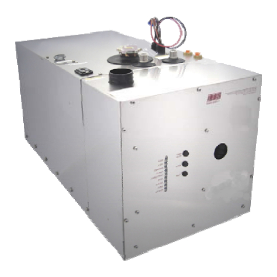
Section Overview Thank you for purchasing the POLAR™ HD Heating Module. This section covers critical information you need to know before beginning the installation including how to protect your Warranty, and tools and equipment needed. Figure 1-1: POLAR™ HD Heating Module International Thermal Research... -
Page 8: Unpacking The Heating Module
This document reflects approved installation techniques, methods, and materials, and applies only to ITR equipment. The POLAR™ HD Heating Module is only guaranteed by ITR if the entire system has been installed according to the requirements and recommendations set out here. -
Page 9: Polar™ Hd Heating Module Features
Any loss of service or damage as a result of any unapproved modification is the responsibility of the installer. ITR accepts no liability for any damage or loss of service resulting from unapproved modifications. - Page 10 Section 1, Overview • Fan assisted sealed combustion chamber is designed to use outside combustion air. • Simple, low amperage draw ignition. • Electronically-controlled system with: • automatic Safety Shutdown; • manual-resettable aquastats for safety overheat protection. • LED indicators on the Control Panel for diagnostics. •...
-
Page 11: Critical Factors
• Ability for technician to easily access and service the product, especially fuel, plumbing, and electrical systems. • After installation, ability to purge coolant and fuel lines and inspect/test entire system using the ITR-supplied Inspection Check Sheet. International Thermal Research... -
Page 12: Equipment, Tools And Skills
12’ with no bends. (See Section 3 – Installing the Exhaust System, for details when bends are present.). • Exhaust collar. • ITR-muffler with straight-through design. • 1/4” supply fuel line, approved rubber or copper. • #10 sheet metal screws or wood screws to mount fan units inside the occupied areas. -
Page 13: Testing And Inspection
Section 1, Overview Testing and Inspection After all components have been properly installed according to standard practices, industry standards, and the recommendations of this Installation and Operating Manual. The POLAR™ HD Heating Module should be test-operated for inspection purposes. For your convenience, you can use the pullout Inspection Check Sheet in this Manual. - Page 14 Section 1, Overview ™ POLAR HD Heating Module...
- Page 15 Section Mounting – POLAR HD Heating ™ Module Before You Begin Plan the location of the POLAR™HD Heating Module and all its major components in advance to ensure the chosen locations are compatible with installation requirements and within the technical specifications.
-
Page 16: Section 2, Mounting The Polar Hd Heating Module
Section 2, Mounting the POLAR™ HD Heating Module Make sure you are familiar with Section 1 – Overview of this Manual. If the system is not installed according to specifications and with the correct equipment, your POLAR™HD Heating Module ! WARNING may not operate properly, safety may be compromised, and your Warranty may be voided. -
Page 17: Figure 2-1 Module Dimensions
Section 2, Mounting the POLAR™ HD Heating Module • POLAR™ HD Heating Module must be mounted in an area that provides unrestricted access to the front panel. Allow space for connection to the fuel and coolant lines, as well as the power and exhaust connections. -
Page 18: What Not To Do
Section 2, Mounting the POLAR™ HD Heating Module Isolate the unit in a closed compartment so that no air from the ! DANGER heater will infiltrate the living areas. • It is recommended that a catchpan be placed under the POLAR™... -
Page 19: Figure 2-2 Module Mounting Brackets
Section 2, Mounting the POLAR™ HD Heating Module Figure 2-2: Module Mounting Brackets International Thermal Research... - Page 20 Section 2, Mounting the POLAR™ HD Heating Module POLAR™ HD Heating Module...
-
Page 21: Section 3, Installing The Exhaust System
For efficient and safe operation of the POLAR™ HD Heating Module follow all recommendations for properly installing the exhaust. Any deviations from these must be approved in advance by ITR. Although the heater’s exhaust produces very low carbon monoxide ! DANGER emissions, caution is still advised: •... -
Page 22: Recommendation For Installation
Section 3, Installing the Exhaust System • In a vehicle, the typical mounting location for the exhaust outlet is under the floor of the POLAR™ HD Heating Module compartment, or on the other side of the vehicle, directly across from the module. Keep in mind you cannot exceed 12’ of exhaust piping, without any bends, or 8’... - Page 23 Section 3, Installing the Exhaust System • Use an ITR-manufactured muffler with a straight-through design. No other muffler is acceptable. • Exhaust outlet is on the bottom of the POLAR™ HD Heating Module, towards the back. The exhaust and outlet are HOT and the surrounding areas...
-
Page 24: What Not To Do
Don’t use more than 8’ of exhaust pipe if 180° of total bends are present. Don’t use any mufflers not supplied or approved by ITR. Don’t over-tighten exhaust clamps or you may crush the POLAR™ HD Heating Module’s exhaust outlet pipe. - Page 25 Section 3, Installing the Exhaust System Installation air-intake adapter underside of the vehicle Locate a suitable location to mount the air-intake adapter. Drill a 2” hole through the floor. Insert the adapter from underneath and use 3 screws to secure against floor. The air entrance of the air-intake assembly shall be guarded or shielded to exclude rain, snow and debris.
-
Page 26: Figure 3-2 The Exhaust Hole Location & Mounting
Section 3, Installing the Exhaust System Figure 3-1: Installing the Exhaust System (Bottom Exhaust) Figure 3-2: The Exhaust Hole Location & Mounting Template (8 gallon model) The POLAR™ HD Heating Module... -
Page 27: Section 4, Installing The Fuel System
For efficient and safe operation of the POLAR™ HD Heating Module, follow all recommendations for properly installing the fuel system. Any deviations from these must be approved in advance by ITR. Use only diesel fuel, furnace oil, or stove oil in the POLAR™ HD ! DANGER Heating Module. -
Page 28: What Not To Do
Section 4, Installing the Fuel System Recommended size for the fuel line is ¼” I.D. The fuel return line should return to the fuel supply tank and should be no larger than ¼” I.D. The following is recommended for the fuel system installation: The fuel supply from the fuel storage tank to the fuel inlet must be NOTICE from a dedicated fuel pickup on the top of the tank. -
Page 29: Procedure
Section 4, Installing the Fuel System Ensure that fuel lines are always protected from contamination by ! CAUTION foreign material. When installing or servicing, seal off ends to prevent contamination. After installing, you may also wish to flush the fuel line to rid it of any air and any foreign material. Procedure To complete the fuel system installation: Install the inline fuel filter. - Page 30 Section 4, Installing the Fuel System POLAR™ HD Heating Module...
- Page 31 Section Installing Fan Heaters – with “Distribution Module” Only Before You Begin ITR makes a variety of fan heaters for individual cabins or areas. There are Cabin heaters and Spacesaver heaters (where space is limited) with varying BTU output. These heaters draw as little as 0.9 amps and deliver 140 cfm.
-
Page 32: Section 5, Installing Fan Heaters
Section 5, Installing Fan Heaters Fan System Operation ITR fans consist of a 12 VDC brushless fan and heater coil similar to a radiator. When the heater unit comes on, the fan draws ambient air from the interior, blows it through the heater coil and back into the interior through a vent. -
Page 33: Multiple Zone Heating
Switches — to enable low, medium and high-speed settings from inside the vehicle; for use with the ITR defrost heater. • Air Ducting — to allow you to install fans in a remote location (i.e. not directly adjacent to the interior space to be heated) and duct the heated air to its output location. -
Page 34: What Not To Do
Allow a minimum 16 square inch (100 cm sq.) opening in the fan heaters’ mounting compartment to allow sufficient intake of air. ITR’s Spacesaver fan (pictured at left) has two mounting brackets welded to the side of the case. It is designed to be mounted... -
Page 35: Procedure
Section 5, Installing Fan Heaters Procedure After choosing the appropriate mounting location and configuration: Mount the fan using #10 sheet metal screws or wood screws, see Figure 5-2: Mounting a Spacesaver Fan. If you are using ducting and a dual air outlet plate for any fan, limit the total length of duct for both outlets to 36”... -
Page 36: Figure 5-2 Mounting A Spacesaver Fan
Section 5, Installing Fan Heaters Figure 5-2: Mounting a Spacesaver Fan Figure 5-3: Installing a Relay for Additional Fan Amperage POLAR™HD Heating Module... -
Page 37: Section 6, Wiring The Electrical System
Section Wiring the Electrical System Before You Begin The POLAR™ HD Heating Module and its electrical Control Board are pre-wired and have been thoroughly tested together as a unit. To review the wiring system for the POLAR™ HD Heating Module, refer to the wiring diagram at the end of this Section 6, Figure 6-1: System Wiring. -
Page 38: 120 Vac
Section 6, Wiring the Electrical System 120 VAC • The POLAR™ HD Heating Module is equipped with two 1500 watt, 120 VAC immersion elements (other voltages and frequencies are available). The connections for the electrical supply are on the top left side of the POLAR™ HD Heating Module, under a cover, labeled AC power. -
Page 39: Main Electronic Control Board
Section 6, Wiring the Electrical System Figure 6-1 System wiring Main Electronic Control Board The main electronic Control Board is mounted onboard the POLAR™ NOTICE HD Heating Module itself. It has no user adjustable components. International Thermal Research... - Page 40 Section 6, Wiring the Electrical System Distribution Module Zone Control Board (optional) • The Distribution Module is controlled by a separate Zone Control Board. See Section 9, Installing the Distribution Module. What NOT to Do Never shut off the POLAR™ HD Heating Module power via an inline NOTICE battery or master switch while the system is running.
-
Page 41: (Optional)
For efficient and safe operation of the POLAR™ HD Heating Module, follow all recommendations for properly installing the plumbing system. Any deviations from these must be approved in advance by ITR. The POLAR™ HD Heating Module when attached to the Distribution ! DANGER... - Page 42 Section 7, Plumbing the System • Ensure a four (4) quart minimum overflow bottle is attached to the filler neck. • The return and supply coolant plumbing connections are on the top of the POLAR™ HD Heating Module and are 1/2” male NPT fittings.
- Page 43 Section 7, Plumbing the System Figure 7-1 Heating Module • All plumbing lines must be run and secured so as to prevent damage, chafing and kinking • Ensure that the coolant flow is adequate through the POLAR™ HD Heating Module and the system. An indication of inadequate flow is, when the POLAR™...
-
Page 44: What Not To Do
Section 7, Plumbing the System • Use heavy-duty heater hose or PEX tubing. Slip-on foam insulation coverings may be used over the hose fittings to reduce heat loss. Secure all hose connections with spring clamps. • Air vents for the fluid circulation system are not supplied, but may be optionally installed to help bleed air from the system. - Page 45 POLAR™ HD Heating Module. Ensure there are no kinks or sharp bends that might restrict the fluid flow. See Figure 7-2: Three Approved Methods of Installing Heater Hose (Consult ITR for Alternative Methods and Products) for methods of attaching the heater hose.
- Page 46 Section 7, Plumbing the System The POLAR™ HD Heating Module...
-
Page 47: Section 8, Operating The Polar Hd Heating Module
Section Operating the POLAR ™ Heating Module This section describes the features, operation and maintenance your POLAR™HD Heating Module. READ THESE INSTRUCTIONS AND SAVE FOR REFERENCE. Features of Your POLAR™HD Heating Module The POLAR™HD Heating Module uses a diesel burner (12 VDC) controlled by a multi-functional electronic controller as the primary source of heating coolant fluid (anti-freeze and water). -
Page 48: Your Heating Module Model
Section 8, Operating the Heating Module • Low pressure fuel system with built-in fuel pump. • Fuel efficient burner capable of burning a wide variety of diesel-based fuels. • Exhaust has minimal smoke and smell. • Fan assisted sealed combustion is designed to use outside combustion air. -
Page 49: Operating Instructions For The Polar™Hd Heating Module
Section 8, Operating the Heating Module serial number identifies the model type through the first series of letters and numbers. The two types of POLAR™HD Heating Modules are: CH50M – POLAR™HD Heating Module 8 Gallon CH50V – POLAR™HD Heating Module 16 Gallon Operating Instructions for the POLAR™HD Heating Module POLAR™HD... -
Page 50: Polar™Hd Heating Module On
Section 8, Operating the Heating Module Turning Power POLAR™HD Heating Module ON • The POLAR™HD Heating Module’s main Control Panel, Figure 8-2: Heating Module Main Control Panel, located on the front of the module contains three push buttons: ON/OFF power, Bypass, and Reset. -
Page 51: Activating The Burner (Primary) And Ac Heat (Secondary) From The Remote Operating Panel
Section 8, Operating the Heating Module 8.5 Activating the Burner (Primary) and AC Heat (Secondary) from the Remote Operating Panel Activating the Burner (Primary Heat Source) • The burner switch on the Remote Operating Panel controls the ON/OFF of the diesel burner (primary heat source). When the burner switch is turned ON, the diesel portion of the POLAR™HD Heating Module will turn ON after ten seconds. -
Page 52: Activating The Cabin Fan Heaters Through The Thermostats
Any thermostat connected to the Distribution Module’s Zone Control Board and calling for heat will cause the cabin fan controlled by that thermostat to be enabled. The ITR cabin fan has a built-in aquastat that prevents the cabin fan from blowing cold air. -
Page 53: Functions Of The Remote Operating Panel
Section 8, Operating the Heating Module • Turn the engine preheat switch on the Remote Operating Panel to the ON position with the burner or AC switch on. The engine preheat pump and coolant pump will be activated once the POLAR™HD Heating Module is in its set operating temperature range. - Page 54 Section 8, Operating the Heating Module Figure 8-3 Remote Operating Panel Burner Switch (Primary Heat Source) • The burner switch on the remote panel controls the ON/OFF of the diesel burner. The Burner LED will turn on when the diesel burner has been activated. AC Element Switch (Secondary Heat Source) (CH50 DM8 used in Tandem) •...
-
Page 55: Functions Of The Heating Module Control Panel
Section 8, Operating the Heating Module the coolant in the POLAR™HD Heating Module has achieved a preset temperature. Burner LED (Green) • When ON, indicates the diesel burner has been activated. AC Heat LED (Green) • When ON, indicates the 120 VAC immersion elements(s) are activated. - Page 56 Section 8, Operating the Heating Module • The power button turns ON/OFF the power to the control board. The Power LED (green) turns ON when the power to the control board is ON. Bypass Button • The bypass button is for authorized service personnel only.
-
Page 57: Functions Of The Distribution Module (Optional) Zone Control Panel
Section 8, Operating the Heating Module 8.11 Functions of the Distribution Module (Optional) Zone Control Panel • The Distribution Module Zone Control Panel, Figure 8-4: Zone Control Panel, contains seven green LED’s for Power, Zone 1, 2, 3, 4 and 5 Thermostat(s), and Domestic Water. •... -
Page 58: 8.12 Maintenance
Section 8, Operating the Heating Module • The power LED turns ON when the power to the Distribution Module Zone Control Board is ON. Zone 1, 2, 3, 4, 5 Thermostat LED’s (Green) • The Zone # LED turns ON when the thermostat in the zone is calling for heat. -
Page 59: Protecting The Heating Module And Distribution Module (Optional)
Section 8, Operating the Heating Module tune-up. It is recommended that the dealer be contacted for this service or if not available, contact ITR for information on service resources. • As a general guide, the regular maintenance items such as... - Page 60 Section 8, Operating the Heating Module Read and follow the anti-freeze manufacturer’s instructions for the type of anti-freeze and mixture recommended for your application. Note that any domestic water in the Distribution Module NOTICE (Optional) will freeze in cold temperatures and will damage the internal parts.
- Page 61 Section 8, Operating the Heating Module • Air in fuel line (white smoke from exhaust or popping sound from exhaust)? • Fuel filter (external) dirty? • Restrict the fuel return line with needle valve or pinch off completely. Burner Starts but Zone Faults •...
- Page 62 Section 8, Operating the Heating Module 8-16 The POLAR™HD Heating Module...
-
Page 63: Installing Your Distribution Module (Optional)
Section Installing the Distribution Module, DM12 Thank you for purchasing the Distribution Module, DM12. This section describes its installation. 9.1 Installing your Distribution Module Equipment, Tools and Skills As the Installer, you must be qualified and authorized to do the NOTICE installation which requires mechanical and electrical knowledge. -
Page 64: Selecting The Distribution Module
Section 9, Installing the Distribution Module • Module must be mounted using four, 1/4” through bolts using 1” diameter fender washers, lock washers and nuts. The module must be mounted in the position as shown against a wall or on the floor. Figure 9-1: Distribution Module, DM12 9.3 Selecting Distribution... -
Page 65: 9.4 Plumbing Installation
Section 9, Installing the Distribution Module • Mount the bracket against a wall using 2 flat head screws. The distribution module zone box will then click onto the bracket. Figure 9-2: Distribution Module Zone Box • The Distribution Module is connected to the Distribution Module Zone Control Board through the electrical connections located at the bottom of the Zone Control Board box. -
Page 66: Figure 9-3 Distribution Module Fittings Location
Section 9, Installing the Distribution Module Figure 9-3: Distribution Module Fittings Location. All fittings on the POLAR™HD Distribution Module require two NOTICE wrenches when tightening. One wrench must be placed on the module fitting and held in place to prevent this fitting from being overstressed. -
Page 67: Figure 9-4 Domestic Hot Water System Plumbing
Section 9, Installing the Distribution Module Figure 9-4 Domestic Hot Water System Plumbing. • The engine heat/pre-heat connections are located on the side of the distribution module. Hot coolant from the engine enters the module at the “engine heat inlet”. The “engine heat outlet”... - Page 68 Section 9, Installing the Distribution Module • The pre-heat pump wires are capped off to prevent accidental shorting. The pre-heat switch on the remote will turn on power to the wires. • The Distribution module contains two connections on the side panel to connect to the POLAR™HD Heating Module.
-
Page 69: Figure 9-7 Connecting Two Heating Loops
Section 9, Installing the Distribution Module Figure 9-7: Connecting two Heating loops. Do not operate the POLAR™HD Heating Module and Distribution NOTICE WARNING NOTICE Module, DM12 (Optional) until coolant is in the POLAR™ HD Heating Module and Distribution Module and all trapped air has been bled. - Page 70 Section 9, Installing the Distribution Module Figure 9-8: Initial fill up system POLAR™HD 3. Open both valves on the Distribution module. 4. Turn ON the diaphragm pump. This will prime the pumps in the POLAR™HD Distribution Module. It may be necessary to fill up the container with more coolant as the air is being bleed from the system.
-
Page 71: 9.6 Electrical Connection
Section 9, Installing the Distribution Module 9.6 Electrical Connection All electrical connections and wiring must comply with normally- WARNING accepted wiring practices, local regulations applicable industry standards. Only a qualified electrical installer should complete the wiring. All field wiring is to be in accordance with any applicable industry standards. - Page 72 Section 9, Installing the Distribution Module • 12 pin connector to Distribution Module (connector cord transitions to a 9 pin connector for the Distribution Module). • 14 pin connector to thermostat and cabin fan connector plug. Cabin Fan leads • The positive (red) lead from each cabin fan is to be attached to one of the trailing cabin fan leads, color coded for zones, from the thermostat and cabin fan connector plug.
-
Page 73: Figure 9-9 Distribution Module Wiring
Section 9, Installing the Distribution Module Figure 9-9: Distribution Module Wiring If the zone board is being used without the distribution module, use the following wiring diagram: International Thermal Research 9-11... -
Page 74: Inspection And Testing
Section 9, Installing the Distribution Module Figure 9-10: Zone Board Wiring (No DM12) Inspection and Testing After all components have been properly installed according to any applicable industry standards, the Distribution Module and POLAR™HD Heating Module should be inspected using the Inspection Check Sheet in this Manual. -
Page 75: 9.9 Hot Water Temperature Adjustment
Section 9, Installing the Distribution Module 9.9 Hot water temperature adjustment The distribution module has the option to adjust the temperature of the domestic hot water outlet. Standard this temperature is set at 120F (49°C). In order to adjust the temperature, the front cover has to be removed. - Page 76 Section 9, Installing the Distribution Module 9-14 The POLAR™HD Heating Module...
- Page 77 ITR by any other party arising out of or in connection with the sale, delivery, use, performance, or repair of the Product, or in connection with any services performed, even if ITR has been advised of the possibility of such damages, whether based upon warranty, contract, or negligence.
- Page 78 If any warrantable failures occur before the expiration of the warranty, the Owner must give notice of such failures to ITR or to the authorized ITR dealer from which the Product was originally purchased, and obtain written approval for the warranty repair.
- Page 79 If you have a service problem, first check the Troubleshooting section of the Owner’s Manual to determine if your problem is addressed. Also ensure you are familiar with the design and installation setup. When calling ITR or the Dealer with a service problem, have the following information ready at hand: •...
- Page 80 Warranty Information International Thermal Research After repair or replacement of the Products still under warranty, ITR will pay return shipping charges. All repairs done under warranty are subject to the terms and conditions of the flat-rate manual. Telephone / Email Service Service information given over the telephone, by fax or by email is given only in good faith as an accommodation to the customer.
Need help?
Do you have a question about the POLAR HD and is the answer not in the manual?
Questions and answers