
Related Manuals for Parker 700-00028-0


Summary of Contents for Parker 700-00028-0
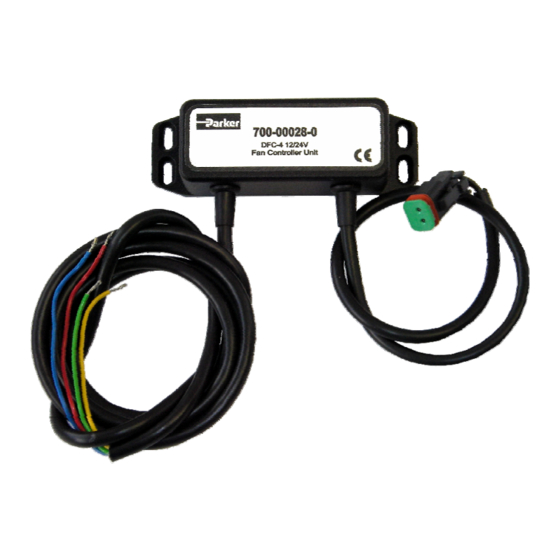
- Page 1 Fan Controller Unit. 700-00028-0 Application and Information Manual. DFC-4, 12/24V Direct Connect option. Publ. 700-00028-0-ver6 February 2006...
- Page 2 Uni-directional, simple cooling systems. By using the 700-00028-0 controller unit and for example, one of the Parker hydraulic motors with integral valving, the cooling system becomes an easy to apply two part system where the fan speed is directly controlled by the engine control unit ( ECU ) PWM output.
-
Page 3: Important Notes
Ensure that any unused wires / terminals are terminated safely and not shorted together. Contact Parker Hannifin sales for more information if you are unsure of connecting this unit. Follow the set-up procedures in this manual for best operational results. -
Page 4: Important Note
The FDS offered by Parker will save fuel, reduce emissions ( particle and noise ) and increase application productivity by only operating the fan when required and matching the fan speed to the heat load that requires dissipation. -
Page 5: Valve Control
Typical characteristic of an inverted pressure control valve This option WILL allow ‘Default- to-full-fan-speed’ safety operation if the power supply to the controller is removed. Recommended Parker valve is the ERA121C30 ( 3000psi operation – other values are available, please consult the IHD catalogue ). INVERSE valve control operation. - Page 6 700-00028-0, DFC-4 Fan Driver Unit. Controller Controller Input to Output Logic Input to Output Logic Adjustment Guide: ( see page 7,8 & 9 for details ). ( see page 7,8 & 9 for details ). I Max 100% Output Characteristics:...
- Page 7 700-00028-0, DFC-4 Fan Driver Unit. Adjustment Location Diagram. Invert Link ‘A’ - Cut if using an inverse operating valve Dither I Min I Max Frequency TOP VIEW OF DRIVER WITH LID REMOVED. 1) Board Style: Parker Unique Size. DFC-4 Specifications:...
- Page 8 Check that ‘Output ON’ led is functioning proportionally by varying the command signal. Set command to maximum PWM % Isolate the controller from the power. Controller 700-00028-0 is now set and ready for operation. Attach the lid to the main controller unit carefully ensuring that seal is maintained.
- Page 9 • Set command to minimum PWM % Isolate the controller from the power. Controller 700-00028-0 is now set and ready for operation. Attach the lid to the main controller unit carefully ensuring that seal is maintained. Replace securing screws and tighten ( Do not over tighten ).
- Page 10 700-00028-0, DFC-4 Fan Driver Unit. Connection Guide: - +10 to +32V supply I/P Blue 0V Supply I/P Green PWM Signal I/P Proportional Yellow PWM 0V I/P valve +10 to +32V max supply input BLUE Proportional 0VDC valve YELLOW GREEN + PWM...
- Page 11 700-00028-0, DFC-4 Fan Driver Unit. Block Diagram: - I Min adjust I Max ( 20 Turn potentiometers ) +Vin Internal PWM ‘ f ’ ‘Dither’ generator 0Vin ( PWM ) frequency Ramp adjust. Generator F.E.T. output ECU PWM stage signal I/P...
- Page 12 Parker Hannifin Corporation Fan Drive Systems 14249 Industrial Parkway Marysville, OH 43040 Customer Service Department Tel: 937-644-4435 Fax: 937-642-3639 www.parker.com/hydraulics/fandrive...
Need help?
Do you have a question about the 700-00028-0 and is the answer not in the manual?
Questions and answers