
Related Manuals for Parker 700-00027-0


Summary of Contents for Parker 700-00027-0
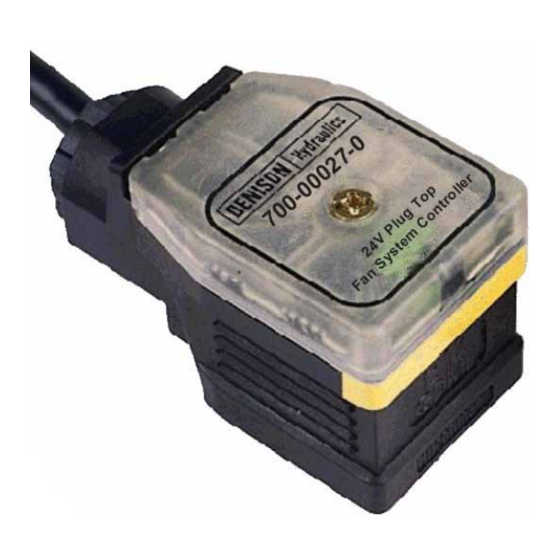
- Page 1 Fan Controller Unit. 700-00027-0 Application and Information Manual. DFC-3, 24V, 600mA Direct Connect option for 20Hz ECM output. Publ. 700-00027-0 July - 2005...
-
Page 2: Product Compatibility
The following ‘Application Hints’ for this versatile driver unit are only issued as a guide and if required, further help and /or advice should be sought from your Local distributor or from Parker Denison internal sales departments. -
Page 3: Product Advantages
Ensure that any unused wires / terminals are terminated safely and not shorted together. Contact Parker Denison for more information if you are unsure of connecting this unit. Fit the supplied rubber gasket correctly between valve coil and plug top driver unit. - Page 4 700-00027-0, DFC-3 Plug Top Driver Unit. INVERTED valve control operation ( Recommended ) INVERTED valve control operation ( Recommended ) Adjustment Guide: Typical characteristic of an inverted pressure control valve This option WILL allow ‘Default- to-full-fan-speed’ safety operation if the power supply to the DFC-3 controller is removed.
- Page 5 700-00027-0, DFC-3 Plug Top Driver Unit. Controller Input / Output Logic Controller Input / Output Logic Adjustment Guide: ( see page 6,7 & 8 for details ). ( see page 6,7 & 8 for details ). I Max 100% 600 mA ( Max )
- Page 6 700-00027-0, DFC-3 Plug Top Driver Unit. Adjustment Location Diagram. ‘Output ON’ led Dither Frequency Adjustment. Fully Anti-Clockwise = approx. 100Hz Fully Clockwise = approx. 250Hz Output Current Adjustment ‘I Max’ ‘I Min’ Clockwise adjustment = adjustment. Increase Output Current Clockwise adjustment = Higher I Min.
- Page 7 700-00027-0, DFC-3 Plug Top Driver Unit. • Plug driver unit onto valve coil to be driven. • Remove ‘DFC-3’ securing screw Adjustment Guide: • Remove ‘DFC-3’ opaque lid to reveal internal adjustments. • Ensure command PWM signal is set to zero.
- Page 8 700-00027-0, DFC-3 Plug Top Driver Unit. • Plug driver unit onto valve coil to be driven. • Remove ‘DFC-3’ securing screw Adjustment Guide: • Remove ‘DFC-3’ opaque lid to reveal internal adjustments. • Remove or cut link A. Negative Logic Negative Logic •...
- Page 9 700-00027-0, DFC-3 Plug Top Driver Unit. 24V supply I/P Blue 0V Supply I/P Green PWM Signal I/P Yellow PWM 0V I/P +24VDC ( +18 to +32V max ) BLUE Rubber gasket 0VDC YELLOW GREEN PWM 0V + PWM output output...
-
Page 10: Mechanical Data
700-00027-0, DFC-3 Plug Top Driver Unit. 34mm 68mm View showing connector configuration. Housing Type:- Self contained DIN ‘Plug Top’ Mechanical Data: Housing Material:- High Impact Resistant Molded ABS. Housing Colour:- Black / dark Grey. Surface Finish:- Matt Housing Thickness:- 2mm ( Mounting Flange and Face ), 1.7mm All Internal Dividers. -
Page 11: Block Diagram
700-00027-0, DFC-3 Plug Top Driver Unit. M3 x 40mm mounting screw Rubber gasket seal in lid recess. Liquid tight cable outlet If required, Apply ‘lithium grease’ under lid ( fill void ) and between driver plug base, gasket and valve coil Driver plug base to valve coil rubber connector. - Page 12 NOTES: Visit us on the web at :- www.parker.com/hydraulics/fandrives...
Need help?
Do you have a question about the 700-00027-0 and is the answer not in the manual?
Questions and answers