Table of Contents
Advertisement
Quick Links
Advertisement
Table of Contents

Related Manuals for Xylem Bell & Gossett e-82SC


Summary of Contents for Xylem Bell & Gossett e-82SC
- Page 1 INSTRUCTION MANUAL P2004729 Series e-82...
-
Page 3: Table Of Contents
Table of Contents Table of Contents 1 Introduction and Safety......................3 1.1 Introduction.......................... 3 1.2 Safety............................. 3 1.2.1 Safety terminology and symbols.................3 1.2.2 Safety instruction decals....................4 1.3 User safety..........................5 1.3.1 Wash the skin and eyes....................6 1.4 Protecting the environment....................6 2 Transportation and Storage...................... - Page 4 Table of Contents 6.5.1 Replacement guidelines.................... 23 6.5.2 Shaft inspection......................23 6.6 Reassembly.........................23 6.6.1 Assemble the standard mechanical seal (e-82-F)...........23 6.6.2 Assemble the box type single mechanical seal (e-82-S)........24 6.6.3 Install the impeller...................... 24 6.6.4 Reinstall the pump assembly..................25 6.6.5 Assemble the flapper valve..................25 6.6.6 Blind flange use......................
-
Page 5: Introduction And Safety
This includes any modification to the equipment or use of parts not provided by Xylem. If there is a question regarding the intended use of the equipment, please contact a Xylem representative before proceeding. -
Page 6: Safety Instruction Decals
1 Introduction and Safety Hazard levels Hazard level Indication A hazardous situation which, if not avoided, will result in DANGER: death or serious injury A hazardous situation which, if not avoided, could result WARNING: in death or serious injury A hazardous situation which, if not avoided, could result CAUTION: in minor or moderate injury Notices are used when there is a risk of equipment... -
Page 7: User Safety
1 Introduction and Safety All series e-82 Pumps All series e-82 with optional ITSC EYEBOLTS OR LIFTING LUGS IF PROVIDED ARE DO NOT RUN PUMP DRY. ROTATING COMPONENTS FOR LIFTING ONLY THE SEAL DAMAGE MAY OCCUR. WARNING COMPONENTS TO WHICH DISCONNECT AND LOCK INSPECT PUMP SEAL THEY ARE ATTACHED. -
Page 8: Wash The Skin And Eyes
• Clean-up of spills Exceptional sites CAUTION: Radiation Hazard Do NOT send the product to Xylem if it has been exposed to nuclear radiation, unless Xylem has been informed and appropriate actions have been agreed upon. Recycling guidelines Always follow local laws and regulations regarding recycling. -
Page 9: Transportation And Storage
2 Transportation and Storage 2 Transportation and Storage 2.1 Examine the delivery 2.1.1 Examine the package 1. Examine the package for damaged or missing items upon delivery. 2. Record any damaged or missing items on the receipt and freight bill. 3. -
Page 10: Long-Term Storage
2 Transportation and Storage Series e-82 Series e-82 with optional ITSC/IT Figure 1: Proper lifting method 2.3 Long-term storage If the unit is stored for more than 6 months, these requirements apply: • Store in a covered and dry location. •... -
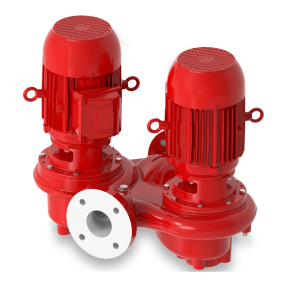
Page 11: Product Description
3 Product Description 3 Product Description 3.1 General description The pump is a centrifugal, in-line, close-coupled pump. These features make the pump easy to install, operate, and service: • High efficiency • Rugged stainless steel-fitted construction • Horizontal or vertical in-line mounting Intended applications WARNING: This product can expose you to chemicals including Lead, which is known to the State of... - Page 12 3 Product Description Table notes 1. An external flush is required on low pressure systems that contain a high concentration of abrasives. 2. For operating temperatures above 250°F, a cooled flush is required and is recommended for temperatures above 225°F for optimum seal life. On closed systems, cooling is accomplished by inserting a small heat exchanger in the flush line to cool the seal flushing fluid.
-
Page 13: Installation
(See the nameplate on the drive unit to select properly-sized overloads.) NOTICE: Supervision by an authorized Xylem representative is recommended to ensure proper installation. Failure to do so may result in equipment damage or decreased performance. Evaluate the installation in order to determine that the Net Positive Suction Head Available... -
Page 14: Piping Checklist
4 Installation Guideline Explanation/comment Keep the pump as close to the liquid source as practically This minimizes the friction loss and keeps the suction possible. piping as short as possible. If the pump is not on a closed system, locate the pump so that the fewest number of bends or elbows in the suction pipe are needed. -
Page 15: Typical Pump Installation
4 Installation Check Explanation/comment Checked For pumps with flanges, check that the bolt holes in — the pump flanges match the bolt holes in the pipe flanges. For pumps mounted in vertical piping with the motor This prevents strain on the pump parts and in the horizontal position, check that adequate piping. - Page 16 4 Installation In many installations, the piping is installed near the ceiling with the pump located close to the floor for ease of maintenance. Pumps with up to 3 inch nozzles and up to 215 NEMA frame motors can be installed in this configuration with pipe hangers adequate to carry the loads from the pump, piping and piping accessories.
- Page 17 4 Installation Pumps with motors 256 NEMA frame and below can be installed with the shaft horizontal and the piping vertical with supports for the piping (not shown) adequate to carry the loads from the pump and piping. See Figure 8: on page 15 Figure 8 Pumps with motors 256 NEMA frame and below can also...
-
Page 18: Typical System Installation
4 Installation 4.3 Typical system installation 1. Expansion tank 2. B&G Rolairtrol ® air separator 3. Supply to system 4. TPV tank purge system 5. B&G Triple Duty ® valve 6. B&G Series e–82 Pump 7. B&G Suction Diffuser Plus 8. -
Page 19: Commissioning, Startup, Operation, And Shutdown
5 Commissioning, Startup, Operation, and Shutdown 5 Commissioning, Startup, Operation, and Shutdown 5.1 Preparation for startup WARNING: • Failure to follow these precautions before you start the unit will lead to serious personal injury and equipment failure. • Do not operate the pump below the minimum rated flows or with the suction or discharge valves closed. -
Page 20: Prime The Pump
5 Commissioning, Startup, Operation, and Shutdown 5.2 Prime the pump CAUTION: Do not run the pump dry. Make sure that the pump body is full of liquid before startup. If the system does not automatically fill the pump body with liquid, then you must manually prime the pump. 1. -
Page 21: Shut Down The Pump
5 Commissioning, Startup, Operation, and Shutdown Operation at reduced capacity WARNING: Never operate any pumping system with a blocked suction and discharge. Operation, even for a brief period under these conditions, can cause confined pumped fluid to overheat, which results in a violent explosion. You must take all necessary measures to avoid this condition. -
Page 22: Maintenance
6 Maintenance 6 Maintenance 6.1 Standby operation The pump unit in use and the one on standby must alternate regularly to ensure even distribution of the hours of operation. Make the change manually or install an automatic controller. When pumping domestic hot water, the pump units should alternate at least once per day to prevent any deposits from clogging the pump unit on standby. -
Page 23: Disassembly Precautions
6 Maintenance 6.4.1 Disassembly precautions This manual clearly identifies accepted methods for disassembling units. These methods must be adhered to. WARNING: • Make sure that the pump is isolated from the system and that pressure is relieved before you disassemble the pump, remove plugs, open vent or drain valves, or disconnect the piping. -
Page 24: Remove The Impeller
When it is necessary to reduce the pump flow rate and generated head by trimming the impeller diameter, the following guidelines apply for stainless steel impellers: • Review the pump hydraulic selection data and consult your local Xylem representative to select the proper reduced diameter. -
Page 25: Replacement Guidelines
6 Maintenance 6.5.1 Replacement guidelines Impeller replacement This table shows the criteria for replacing the impeller: Impeller parts When to replace Impeller vanes • When grooved deeper than 1/16 in. (1.6 mm), or • When worn evenly more than 1/32 in. (0.8 mm) Vane edges When you see cracks, pitting, or corrosion damage Gaskets, O-rings, and seats replacement... -
Page 26: Assemble The Box Type Single Mechanical Seal (E-82-S)
6 Maintenance 6. Impeller 7. Impeller lockwasher 8. Volute 9. Impeller capscrew 10.Volute gasket 11.Impeller washer 12.Shaft sleeve 13.Shaft Figure 11: Standard mechanical seal 6.6.2 Assemble the box type single mechanical seal (e-82-S) 1. Lubricate the shaft sleeve and seal cap with soapy water. Do not use a petroleum lubricant. -
Page 27: Reinstall The Pump Assembly
6 Maintenance 6.6.4 Reinstall the pump assembly 1. Install a new volute gasket. 2. Install the pump assembly into the volute. 3. Tighten the volute capscrews according to the Capscrew torque table. 4. Install a seal flushing tube. 5. Install the drain plug. 6. -
Page 28: Screw Torque Values
6 Maintenance 6.6.6.2 Remove the blind flange 1. Shut down the pump. See Shut down the pump on page 19. 2. Drain the pump. See Drain the pump on page 21. 3. Remove the blind flange. Dispose of the used gasket. Save the capscrews for pump assembly reinstallation. -
Page 29: Troubleshooting
7 Troubleshooting 7 Troubleshooting 7.1 Precautions WARNING: Maintenance and service must be performed by skilled and qualified personnel only. 7.2 The pump unit is turned on but does not work Cause Remedy Power supply cut off Restore the power supply The thermal overload protection of the motor has been Reset the thermal overload protection in the control triggered... -
Page 30: The Thermal Overload Protection Of The Motor Is Triggered Occasionally, Or After The Pump Unit Has Been Running For A Few Minutes
7 Troubleshooting 7.5 The thermal overload protection of the motor is triggered occasionally, or after the pump unit has been running for a few minutes Cause Remedy It is calibrated at a value too low in relation to the rated Recalibrate current of the motor Input voltage outside the rated limits... -
Page 31: The Pump Starts Up Too Frequently (Automatic Start/Stop)
• Undersized, or • Install an expansion vessel • Not installed Pump unit oversized Contact Xylem or the Authorized Distributor 7.10 The pump unit never stops (automatic start/stop) Cause Remedy The required flow rate s greater than the one expected... -
Page 32: The Motor Becomes Excessively Hot
7 Troubleshooting 7.12 The motor becomes excessively hot Cause Remedy Room temperature outside the rated limits Lower the room temperature Cooling fan of the motor clogged or damaged Clean or replace the cooling fan The pump unit starts up too frequently See Part 7.8 The frequency converter, if present, has not been See the frequency converter manual... -
Page 33: Product Warranty
8 Product Warranty 8 Product Warranty Commercial warranty Warranty. For goods sold to commercial buyers, Seller warrants the goods sold to Buyer hereunder (with the exception of membranes, seals, gaskets, elastomer materials, coatings and other "wear parts" or consumables all of which are not warranted except as otherwise provided in the quotation or sales form) will be (i) be built in accordance with the specifications referred to in the quotation or sales form, if such specifications are expressly made a part of this Agreement, and (ii) free from defects in material and... - Page 34 8 Product Warranty materials, coatings and other "wear parts" or consumables all of which are not warranted except as otherwise provided in the quotation or sales form) will be free from defects in material and workmanship for a period of one (1) year from the date of installation or eighteen (18) months from the product date code, whichever shall occur first, unless a longer period is provided by law or is specified in the product documentation (the “Warranty”).
- Page 36 The original instruction is in English. All non-English instructions are translations of the original instruction. Tel: (847) 966–3700 Fax: (847) 965–8379 © 2020 Xylem Inc www.xylem.com/bellgossett Bell & Gossett is a trademark of Xylem Inc or one of its subsidiaries. P2004729_en-US_2020-09_Series e-82...
Need help?
Do you have a question about the Bell & Gossett e-82SC and is the answer not in the manual?
Questions and answers