Advertisement
Advertisement

Subscribe to Our Youtube Channel
Related Manuals for Xylem Lowara e1631


Summary of Contents for Xylem Lowara e1631
- Page 1 K20040028 REV.0...
-
Page 2: Table Of Contents
en - Translation of the original instructions Installation, Operation, and Maintenance Manual......3 1 Introduction and Safety............... 3 2 Transportation and Storage............4 3 Product Description..............4 4 Installation...................5 5 Commissioning, Startup, Operation, and Shutdown....8 6 Maintenance................8 7 Troubleshooting................9 e1631 Installation, Operation, and Maintenance Manual... -
Page 3: Introduction And Safety
Hazard levels 1.6 EC DECLARATION OF CONFORMITY Hazard level Indication XYLEM SERVICE ITALIA S.R.L., WITH HEADQUARTERS IN VIA VIT- TORIO LOMBARDI 14 - 36075 MONTECCHIO MAGGIORE VI - ITA- A hazardous situation which, if not DANGER: LIA, HEREBY DECLARES THAT THE FOLLOWING PRODUCT:... -
Page 4: Transportation And Storage
Machi- nery directive 2006/42/EC. The person making the coupling rev.01 is responsible for all safety aspects of the combined unit. Lowara is a trademark of Xylem Service Italia S.R.L., subsidiary of Xy- 2.3 Storage guidelines lem Inc. Storage location... - Page 5 en - Translation of the original instructions • Liquids not compatible with the pump construction materials Standard/ Material Material EN733 Extension • Hazardous liquids (such as toxic, explosive, flammable, or corro- Optional code casing/ range range sive liquids) impeller 32–125 to 200–250, •...
-
Page 6: Installation
en - Translation of the original instructions The following equation is used to calculate the maximum height above 4 Installation the liquid level which the pump can be installed: (p *10.2 - Z) ≥ NPSH + H + H + 0.5 Precautions Barometric pressure in bar (in closed system is system pres- WARNING:... - Page 7 en - Translation of the original instructions 4.2 Electrical requirements Frequency Hz Phase ~ UN [V] ± % • The local regulations in force overrule these specified require- 220 – 240 ± 6 ments. 230/400 ± 10 • In the case of fire fighting systems (hydrants and/or sprinklers), check the local regulations in force.
-
Page 8: Commissioning, Startup, Operation, And Shutdown
en - Translation of the original instructions Note: NOTICE: • If the transmission of vibrations can be disturbing, provide vibra- • Never operate the pump below the minimum rated flow, when dry, tion-damping supports between the pump and the foundation. or without prime. -
Page 9: Maintenance
en - Translation of the original instructions 6 Maintenance Cause Remedy There are foreign objects (solids or Contact the Sales and Service Precautions fibrous substances) inside the Department. pump which have jammed the im- Electrical Hazard: peller. Disconnect and lock out electrical power before installing or The pump is overloaded because Check the actual power require- servicing the unit. - Page 10 en - Translation of the original instructions 7.9 The electric pump stops, and then rotates Cause Remedy in the wrong direction A power phase is missing. Check the • power supply • electrical connection Cause Remedy There is a leakage in one or both of the follow- Repair or replace the ing components: faulty component.
- Page 11 e1631 4A 15kW 2P... e1631 4A 18.5kW 2P... e1631 4A 22kW 2P... e1631 4A 2.2kW 4P... e1631 4A 3kW 4P... e1631 4A 4kW 4P... e1631 4B 5.5kW 4P... e1631 4B 7.5kW 4P... e1631 4C 7.5kW 4P... e1631 4C 11kW 4P... e1631 5B 5.5kW 4P...
- Page 12 e1631 4A 30kW 2P... e1631 4B 37kW 2P... e1631 4B 45kW 2P... e1631 4B 55kW 2P... e1631 4C 75kW 2P... e1631 4C 90kW 2P... e1631 5B 45kW 2P... e1631 5B 55kW 2P... e1631 5B 75kW 2P... e1631 5B 90kW 2P... e1631 5D 18.5kW 4P...
- Page 13 e1631 4D 11kW 4P... e1631 4D 15kW 4P... e1631 4D 18.5kW 4P... e1631 4D 22kW 4P... e1631 4D 30kW 4P... e1631 4E 30kW 4P... e1631 4E 37kW 4P... e1631 4E 45kW 4P... e1631 5E 37kW 4P... e1631 5E 45kW 4P... e1631 5E 55kW 4P...
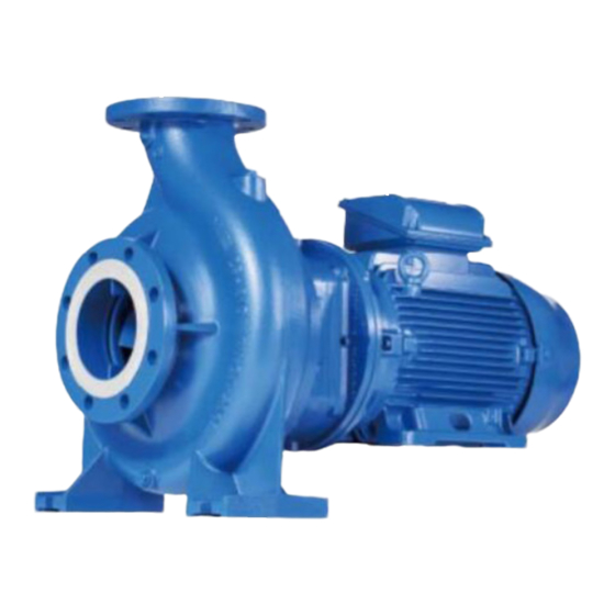
- Page 14 Technical appendix Washer Safety guard Motor Hexagonal head screw Stud bolt Plug Grub screw Hexagonal nut Impeller nut e1610 45KW e1631 1. Pump series 8. Motor insulation 12. Flow-Passage 4. Motor power KW e1610= Frame mounted class material e1631= Stub shaft F = F级...
- Page 15 Technical appendix English 1..Wear ring clearance 2..Discharge port 3..Casing cover 4..Shaft 5..Bearing bracket 6..Suction port 7..Impeller 8..Mechanical seal 9..Motor 10.. Ball bearings, inside drive e1631 Installation, Operation, and Maintenance Manual...
- Page 16 Technical appendix Dimensioni Potenza del mo- Velocità Tipo di installa- Tipo di installa- Dimensioni tenu- Peso pompa zione zione tore [rpm] [kg] [kW] Orizzontale Verticale [mm] e1631 4A 15kW 2P... 2950 e1631 4A 18.5kW 2P... 18,5 2950 e1631 4A 22kW 2P... 2950 e1631 4A 30kW 2P...
- Page 17 Technical appendix Dimensioni Potenza del mo- Velocità Tipo di installa- Tipo di installa- Dimensioni tenu- Peso pompa tore zione zione [rpm] [kg] [kW] Orizzontale Verticale [mm] e1631 6D 37kW 4P... 1450 e1631 6D 45kW 4P... 1450 e1631 6E 55kW 4P... 1450 e1631 6E 75kW 4P...
- Page 18 Technical appendix T [° C] Hv [m] 10,3 14,6 20,2 Istallazione corretta Istallazione non corretta Riduzione eccentrica Curva stretta; elevata resistenza di flusso Immersion insufficiente; aspirazione aria Pendenza positiva Buona immersione Pendenza positiva; sacche d'aria Curva larga Diametro del tubo < diametro bocca della pompa; elevata resistenza di flusso Diametro tubo d'aspirazione >...
- Page 19 Technical appendix e1631 Installation, Operation, and Maintenance Manual...
- Page 20 Technical appendix ² Dimensioni Motore Velocità Flangia di aspirazione Flangia di scarico Potenza [rpm] [kNm] ø ø [kN] [kN] [kN] [kN] [kN] [kN] [kN] [kN] [kNm] [kW] 2950 e1631 4A 15kW 2P... 18,5 2950 e1631 4A 18.5kW 2P... 2950 e1631 4A 22kW 2P... 2950 e1631 4A 30kW 2P...
- Page 21 Technical appendix Motore Flangia di aspirazione Flangia di scarico Dimensioni Velocità Potenza [rpm] [kNm] ø ø [kN] [kN] [kN] [kN] [kN] [kN] [kN] [kN] [kNm] [kW] e1631 4A 3kW 4P... 1450 1450 e1631 4A 4kW 4P... 1450 e1631 4B 5.5kW 4P... 1450 e1631 4B 7.5kW 4P...
- Page 22 Technical appendix Flangia di aspirazione Flangia di scarico Dimensioni Motore Velocità Potenza [rpm] [kNm] ø [kNm] ø [kN] [kN] [kN] [kN] [kN] [kN] [kN] [kN] [kW] e1631 6C 22kW 4P... 1450 1450 e1631 6C 30kW 4P... 1450 e1631 6D 30kW 4P... 1450 e1631 6D 37kW 4P...
- Page 23 Technical appendix Motore Velocità Flangia di aspirazione Flangia di scarico Dimensioni Poten- [rpm] ø [kN] [kN] [kN] [kN] [kNm] ø [kN] [kN] [kN] [kN] [kNm] [kW] 2950 e1631 5B 45kW 2P... 2950 e1631 5B 55kW 2P... 2950 e1631 5B 75kW 2P... 2950 e1631 5B 90kW 2P...
- Page 24 Technical appendix Dimensioni Motore Velocità Flangia di aspirazione Flangia di scarico Poten- [rpm] ø [kN] [kN] [kN] [kN] [kNm] ø [kN] [kN] [kN] [kN] [kNm] [kW] e1631 5E 45kW 4P... 1450 1450 e1631 5E 55kW 4P... 1450 e1631 5E 75kW 4P... 1450 e1631 6B 11kW 4P...
- Page 25 Technical appendix 100-160 - 150-400 200-250 - 200-315 - 250-315 G 3/8" Drenaggio G 1/2" G 1/2" Scarico punto di presa di pressione G 1/4" Uscita circolazione G 1/4" G 1/2" G 1/4" G 1/2" Aspirazione punto di presa di pres- sione Punto di riempimento G 3/8"...
- Page 26 Technical appendix English Gauge plug PM1 Drain plug E Fill plug F English Gauge plug PM1 Drain plug E Fill plug F e1631 Installation, Operation, and Maintenance Manual...
- Page 27 Technical appendix e1631 Installation, Operation, and Maintenance Manual...
- Page 28 Technical appendix Dimensioni Poten- Velo- A / 922 B / 901.01 C / 920.02 D / 901.03 G / 901.02 H / 901.05 I / 904.01 E, F, T / CO1, PM1, za del cità 920.01 920.03 904.02 903.01, motore 903.04 903.02, .
- Page 29 Technical appendix Dimensioni Poten- Velo- A / 922 B / 901.01 C / 920.02 D / 901.03 G / 901.02 H / 901.05 I / 904.01 E, F, T / CO1, PM1, za del cità 920.01 920.03 904.02 903.01, motore 903.04 903.02, .
- Page 30 Technical appendix Dimensioni Poten- Velo- A / 922 B / 901.01 C / 920.02 D / 901.03 G / 901.02 H / 901.05 I / 904.01 E, F, T / CO1, PM1, za del cità 920.01 920.03 904.02 903.01, motore 903.04 903.02, .
- Page 31 Technical appendix Dimensioni Poten- Velo- A / 922 B / 901.01 C / 920.02 D / 901.03 G / 901.02 H / 901.05 I / 904.01 E, F, T / CO1, PM1, za del cità 920.01 920.03 904.02 903.01, motore 903.04 903.02, .
Need help?
Do you have a question about the Lowara e1631 and is the answer not in the manual?
Questions and answers