Table of Contents
Advertisement
Quick Links
Advertisement
Table of Contents

Subscribe to Our Youtube Channel
Related Manuals for Xylem GOULDS e-SVE Series


Summary of Contents for Xylem GOULDS e-SVE Series
- Page 1 INSTRUCTION MANUAL IM326 Smart Pump Range Variable Speed Pump Unit...
-
Page 3: Table Of Contents
Table of Contents Table of Contents 1 Introduction and Safety......................3 1.1 Introduction.......................... 3 1.2 Safety............................. 3 1.2.1 Safety message levels....................3 1.2.2 User safety........................4 1.2.3 Wash the skin and eyes....................5 1.3 Protecting the environment....................5 2 Transportation and Storage...................... 7 2.1 Examine the delivery......................7 2.1.1 Examine the package.................... - Page 4 Table of Contents 6.5.1 Main Visualization....................... 27 6.5.2 Parameters menu visualization................. 28 6.5.3 Alarms and errors visualization................. 29 6.6 Software parameters......................30 6.6.1 Status parameters....................... 30 6.6.2 Settings parameters....................33 6.6.3 Drive configuration parameters................34 6.6.4 Sensor configuration parameters................36 6.6.5 RS485 Interface parameters..................38 6.6.6 Multi-pump configuration parameters..............39 6.6.7 Test run configuration....................
-
Page 5: Introduction And Safety
This includes any modification to the equipment or use of parts not provided by Xylem. If there is a question regarding the intended use of the equipment, please contact a Xylem representative before proceeding. -
Page 6: User Safety
1 Introduction and Safety Safety message level Indication A hazardous situation which, if not avoided, could result WARNING: in death or serious injury A hazardous situation which, if not avoided, could result CAUTION: in minor or moderate injury The possibility of electrical risks if instructions are not Electrical Hazard: followed in a proper manner •... -
Page 7: Wash The Skin And Eyes
• Clean-up of spills Exceptional sites CAUTION: Radiation Hazard Do NOT send the product to Xylem if it has been exposed to nuclear radiation, unless Xylem has been informed and appropriate actions have been agreed upon. Smart Pump Range INSTRUCTION MANUAL... - Page 8 1 Introduction and Safety Recycling guidelines Always follow local laws and regulations regarding recycling. Waste and emissions guidelines Do not dispose of equipment containing electrical components together with domestic waste. Collect it separately in accordance with local and currently valid legislation. Smart Pump Range INSTRUCTION MANUAL...
-
Page 9: Transportation And Storage
2 Transportation and Storage 2 Transportation and Storage 2.1 Examine the delivery 2.1.1 Examine the package 1. Examine the package for damaged or missing items upon delivery. 2. Record any damaged or missing items on the receipt and freight bill. 3. -
Page 10: Storage Guidelines
2 Transportation and Storage e-SVE e-HME Figure 1: Lifting 2.3 Storage guidelines Storage location The product must be stored in a covered and dry location free from heat, dirt, and vibrations. NOTICE: Protect the product against humidity, heat sources, and mechanical damage. NOTICE: Do not place heavy weights on the packed product. -
Page 11: Product Description
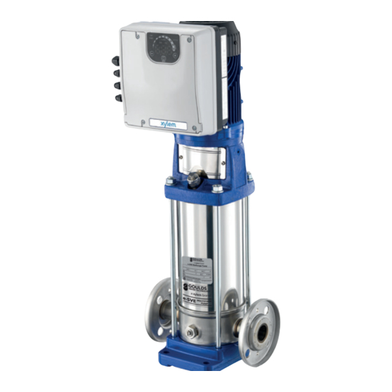
3 Product Description 3 Product Description 3.1 General description This product is a variable speed pump unit and can be installed vertically or horizontally. It is non self-priming. 3.2 Intended use The product can be used to pump: • Cold water •... -
Page 12: Motor Specifications
3 Product Description 3.4.1 Motor specifications Motor data plates XYLEM SERVICE ITALIA SRL P. 19 VIA VITTORIO LOMBARDI 14 36075 MONTECCHIO MAGGIORE (VI) - ITALY Reg. No. 0752056096 E481622 MADE IN ITALY Type : P. 1 Code : P. 2 S/N : P. -
Page 13: Pump Specifications
AB Hz FLUID ° SINGLE PHASE – AMB TEMP -15°C TO 45°C THREE PHASE – AMB TEMP -15°C TO 50°C XYLEM INC. 1 GOULDS DR. AUBURN, NY USA www.xylem.com/goulds 1. Catalog number 2. Capacity Range 3. TDH Range 4. Rated Speed 5. -
Page 14: Design And Layout
3 Product Description 3.5 Design and layout The unit can be fitted with the features required by the application. Figure 2: Main components — single-phase and three-phase models Table 1: Description of components Position number Description Tightening torque ± 15% [Nm] [in•lbs] Screw... - Page 15 3 Product Description Pre-assembled factory components Component Quantity Notes Plug for cable gland 0.145–0.275 in (3.7 to 7.0 mm) Cable gland and lock 0.177–0.394 in (4.5 Cable out diameter to 10.0 mm) Cable gland 0.265–0.512 in (7.0 to 13.0 mm) Optional components Table 2: Optional components Component...
-
Page 16: Installation
4 Installation 4 Installation 4.1 Mechanical installation 4.1.1 Installation area DANGER: Potentially explosive atmosphere hazard. The operation of the unit in environments with potentially explosive atmospheres or with combustible dusts (e.g.: wood dust, flour, sugars and grains) is strictly forbidden. WARNING: •... -
Page 17: Hydraulic Installation
4 Installation Figure 3: Permitted positions Minimum spacing Area e-SM Drive model Free distance Above the unit 103..105..107..111..115 > 10.2 in (260 mm) Center-distance between units (to 103..105..107..111..115 > 10.2 in (260 mm) ensure space for cabling) 303..305..307..311..315..322 ≥ 11.8 in (300 mm) 4.2 Hydraulic installation The following images show a single pump system and a multi-pump system respectively. -
Page 18: Electrical Installation
4 Installation Figure 5: Multi-pump system 1. Pump with e-SM Smart Motor drive 2. Diaphragm pressure tank 3. Distribution panel 4. On-Off valve 5. Non-return valve 6. Low water control 7. Pressure gauge 8. Pressure sensor 9. Drain tap Pressure tank On the pump delivery side there is a membrane expansion vessel, which gives the possibility of maintaining the pressure inside the piping when the system is not being used. -
Page 19: Wire Types And Ratings
4 Installation – A high-sensitivity differential switch (30 mA) [residual current device RCD] suitable for earth fault currents with DC or pulsating DC content (a Type B RCD is suggested). – A mains isolator switch with a contact gap of at least 0.12 in (3 mm). The electrical control panel checklist NOTICE: The control panel must match the ratings of the electric pump. -
Page 20: Power Supply Connection
4 Installation Control cables External volt free contacts must be suitable for switching < 10 VDC. NOTICE: • Install the control cables separate from the power supply cables and the fault signal relay cable • If the control cables are installed in parallel with the power supply cable or the fault signal relay, the distance between the cables must exceed 200 mm Do not intersect the power supply cables;... - Page 21 4 Installation 10 A 208÷240 380÷460 Figure 6: Wiring diagrams Smart Pump Range INSTRUCTION MANUAL...
- Page 22 4 Installation 9 10 11 12 13 14 15 16 17 18 19 20 25 24 23 22 21 20 19 18 17 16 15 14 13 12 11 10 9 Figure 7: Connection label Table 7: 1~ I/O terminals Item Terminals Ref.
- Page 23 4 Installation Item Terminals Ref. Description Notes Analog input P2IN/S+ Actuator mode 0-10 V 0-10 VDC input 0-10V P2C/S- GND for 0-10 V input GND, electronic ground (for S+) External Pressure Power supply external 15VDC, Ʃ max. 100 sensor [also sensor +15 VDC Differential] External sensor 4-20...
- Page 24 4 Installation Item Terminals Ref. Description Notes External pressure Power supply external 15VDC, Ʃ max. 100 sensor sensor +15 VDC Sensor 4-20 mA input 4-20 mA External Start/Stop Start External ON/OFF Default short circuited input Pump is enabled to Stop External ON/OFF input reference External Lack of Water LoW+...
-
Page 25: Operation
• duty points insisting on unit maximum power • persisting undervoltage of mains, the life of the unit may be jeopardized and/or derating may occur: for further information contact Xylem or the Authorised Distributor. 5.2 Wait times Electrical Hazard: Contact with electric components may cause death, even after the unit has been switched off. -
Page 26: System Setup And Operation
6 System Setup and Operation 6 System Setup and Operation 6.1 Programming precautions NOTICE: • Carefully read and adhere to the following instructions before starting the programming activities to avoid incorrect settings that can cause malfunctions. • All modifications must be done by qualified technicians. 6.2 Control panel description Figure 8: Control panel Position number... -
Page 27: Led Description
6 System Setup and Operation Push button Function • Main view (see parameter 6.4.1): decreases the required value for the selected control mode • Parameter menu (see parameter 6.4.2): decreases the displayed parameter index • Parameter view / editing (see parameter 6.4.2): decreases the value of the displayed parameter •... -
Page 28: Com (Communication)
6 System Setup and Operation LED bar Status First LED flashing Motor in operation; the speed is lower than the absolute minimum, P27 Motor stopped 6.4.4 COM (communication) Condition 1 • The communication bus protocol is the Modbus RTU protocol; the P50 parameter is set to the Modbus value •... -
Page 29: Units Of Measurement
6 System Setup and Operation 6.4.5 Units of measurement LED on Measurement active Notes 10xRPM Impeller rotation speed The display shows the speed in 10xRPM Hydraulic head The display shows the value of the head in bar The display shows the value of the head in psi 6.5 Display 6.5.1 Main Visualization... -
Page 30: Parameters Menu Visualization
6 System Setup and Operation Display Mode Description Pump on; the motor starts following the selected control mode. It appears for a few seconds when contacts 11 and 12 (see Par. 5.4) are short circuited and the pump is not in STOP mode. -
Page 31: Alarms And Errors Visualization
6 System Setup and Operation Parameter Description Power on If after switching ON, parameter Menu View is accessed with P23 = ON, P20 flashes: P20 → P20. Enter the password to display and change the parameters. Password timeout If with P23 = ON no button is pressed for over 10 minutes from the last parameter Menu View, both the view and the editing of the parameters are disabled. -
Page 32: Software Parameters
6 System Setup and Operation 6.6 Software parameters Mark Parameter type No mark Applicable to all units. Global parameter, shared by all pumps in the same multi-pump system Read only 6.6.1 Status parameters Parameter number Parameter name Unit of measurement Description Required value bar/psi/ rpmx10... - Page 33 6 System Setup and Operation Parameter number Parameter name Unit of measurement Description Regulation Restart Value It defines the start value [0-100] after the stop of the pump, as a percentage of the P01 value. If the required value is met and there is no further consumption, then the pump stops.
- Page 34 6 System Setup and Operation Parameter number Parameter name Unit of measurement Description 1st error This parameter stores the last error occurred in chronological order. The information displayed switches through the values: • (Exx): xx indicates the error code • (Hyy): yy is the value of hours referred to P05- P06 when the error Exx happened...
-
Page 35: Settings Parameters
6 System Setup and Operation 6.6.2 Settings parameters Parameter number Parameter name Description Password entering [0-999] The user can enter here the system password, which gives access to all system parameters: this value is compared with the one stored in P22. When a correct password is entered, the system remains unlocked for 10 minutes. -
Page 36: Drive Configuration Parameters
6 System Setup and Operation 6.6.3 Drive configuration parameters Parameter number Parameter name Unit of measurement Description Control mode [ACT, HCS, MSE, This parameter sets the Control Mode (default value: MSY] HCS) ACT: Actuator mode. • A single pump maintains a fixed speed at any flow rate. - Page 37 6 System Setup and Operation Parameter number Parameter name Unit of measurement Description Min RPM set rpmx10 Minimum pump speed setup. [Min*-ACT set] Ramp 1 [1–250] This parameter adjusts the fast acceleration time. It affects the control of the pump for HCS, MSE and MSY control modes (also see Par.
-
Page 38: Sensor Configuration Parameters
6 System Setup and Operation Parameter number Parameter name Unit of measurement Description Smin time [0-100] This parameter sets the time delay before a shut-off below P27 occurs. ® It is only used by the Hydrovar controller if P34 = STP. It affects the control of the pump for HCS, MSE and MSY control modes. - Page 39 6 System Setup and Operation Parameter number Parameter name Unit of measurement Description Zero Pressure Auto- bar/psi This parameter lets the user Calibration perform the initial auto- calibration of the pressure sensor. It is used to compensate for the offset signal of the sensor at zero pressure caused by the tolerance of the sensor itself.
-
Page 40: Rs485 Interface Parameters
6 System Setup and Operation Parameter number Parameter name Unit of measurement Description Lack Of Water Switch Input This parameter enables/ [DIS, ALR, ERR] disables the management of the lack of water input (see Par. 4.3.3, terminals 13 and 14). It defines the behaviour of the unit when the lack of water input is enabled and... -
Page 41: Multi-Pump Configuration Parameters
6 System Setup and Operation Parameter name Parameter number Unit of measurement Description Communication protocol - This parameter sets the Address [1-247]/[0-127] desired address for the unit, when connected to an external device, depending on the protocol selected in P50: •... - Page 42 6 System Setup and Operation Multipump – Switch Setpoint of the main pump Interval [0-250] forced switch interval. If the pump with priority 1 works in continuous mode until this time is reached, the switch between this pump and the next is forced.
-
Page 43: Test Run Configuration
6 System Setup and Operation Multipump – Priority This parameter shows the pump priority value within the multi-pump set. This parameter displays the following information: Pr1 (Pr1) .. Pr3 (Pr3) or Pr0 (Pr0) where: • Pr1 .. PR3, indicate that the pump is communicating with other pumps of the... - Page 44 6 System Setup and Operation Parameter number Parameter name Unit of measurement Description Avoid Frequent Parameters This parameter limits the Saving [NO, YES] frequency with which the unit stores the required value P02 in the EEPROM memory, in order to extend its life.
-
Page 45: Maintenance
7 Maintenance 7 Maintenance 7.1 Precautions Electrical Hazard: • Before attempting to use the unit, check that it is unplugged and that the pump and the control panel cannot restart, even unintentionally. This also applies to the auxiliary control circuit of the pump. •... -
Page 46: Troubleshooting
1. Reset the default parameters using parameter P68 2. Wait 10 s 3. Restart the pump If the problem continues, contact Xylem or the Authorised Distributor LOW alarm Lack of water detection (if Check the water level inside P48= ALR) -
Page 47: Error Codes
Stop the pump for 5 error lost minutes and then restart it again; if the problem continues, contact Xylem or the Authorised Distributor Motor overload error • High motor current Stop the pump for 5 minutes and then restart it •... - Page 48 Generic hardware error Hardware error Stop the pump for 5 minutes and then restart it again; if the problem continues, contact Xylem or the Authorised Distributor LOW error Lack of water detection (if Check the water level inside P48= ERR)
-
Page 49: Technical Specification
9 Technical Specification 9 Technical Specification 9.1 Electrical and environmental specifications e-SM Drive model Input Input 50/60 ± 2 frequency [Hz] Main supply L1 L2 L1 L2 L3 Nominal input 208-240 ±10% 208-240 / 380-460 ±10% 380-460 voltage [V] ±10% Maximum See data plate current... -
Page 50: Dimensions And Weights
9 Technical Specification e-SM Drive model Operating -4-122 / -20-50 temperature [°F] /[°C] Air Pollution Pollution Degree 2 Installation < 3280 / 1000 altitude a.s.l. Derating may occur at higher altitudes [ft] / [m] 9.2 Dimensions and weights 8.82 (224) 3.15 (80) 4.61 (117) 8.82 (224) - Page 51 9 Technical Specification Table 11: Dimensions and weights Model Net weight (motor + drive) [lb (kg)] in. (mm) ESM80... 80...HM 80...HM 16.53 19.84 28.66 31.97 35.27 10.35 3.54 3.11 3.94 4.92 HMHA HA US HA EU (7.5) (13) (14.5) (16) (263) (90) (79)
- Page 52 For more information on how Xylem can help you, go to www.xylem.com Xylem Inc. Visit our Web site for the latest version of this document...
Need help?
Do you have a question about the GOULDS e-SVE Series and is the answer not in the manual?
Questions and answers
I keep getting A-7 error code