Xylem Bell & Gossett e-80 Series Instruction Manual
Hide thumbs
Also See for Bell & Gossett e-80 Series:
- Instruction manual (2 pages) ,
- Quick manual (8 pages)
Table of Contents
Advertisement
Advertisement
Table of Contents

Related Manuals for Xylem Bell & Gossett e-80 Series


Summary of Contents for Xylem Bell & Gossett e-80 Series
- Page 1 INSTRUCTION MANUAL P2002877 Rev C Series e-80...
-
Page 3: Table Of Contents
Table of Contents Table of Contents 1 Introduction and Safety......................3 1.1 Introduction.......................... 3 1.2 Safety............................. 3 1.2.1 Safety terminology and symbols.................3 1.2.2 Safety instruction decals....................4 1.2.3 User safety........................5 1.2.4 Protecting the environment..................6 2 Transportation and Storage...................... 7 2.1 Examine the delivery......................7 2.1.1 Examine the package.................... - Page 4 Table of Contents 6.3.2 Shaft and sleeve inspection..................24 6.4 Reassembly.........................24 6.4.1 Assemble the standard mechanical seal (e-80-F)...........24 6.4.2 Assemble the single mechanical seal (e-80-S)............25 6.4.3 Assemble the box type single mechanical seal (e-80-S)........25 6.4.4 Assemble the double mechanical seal (e-80-D)............. 26 6.4.5 Assemble the packed stuffing box (e-80-PF)............
-
Page 5: Introduction And Safety
This includes any modification to the equipment or use of parts not provided by Xylem. If there is a question regarding the intended use of the equipment, please contact a Xylem representative before proceeding. -
Page 6: Safety Instruction Decals
1 Introduction and Safety Hazard levels Hazard level Indication A hazardous situation which, if not avoided, will result in DANGER: death or serious injury A hazardous situation which, if not avoided, could result WARNING: in death or serious injury A hazardous situation which, if not avoided, could result CAUTION: in minor or moderate injury Notices are used when there is a risk of equipment... -
Page 7: User Safety
1 Introduction and Safety All series e-80 Pumps All series e-80 with optional ITSC EYEBOLTS OR LIFTING LUGS IF PROVIDED ARE DO NOT RUN PUMP DRY. ROTATING COMPONENTS FOR LIFTING ONLY THE SEAL DAMAGE MAY OCCUR. WARNING COMPONENTS TO WHICH DISCONNECT AND LOCK INSPECT PUMP SEAL THEY ARE ATTACHED. -
Page 8: Protecting The Environment
• Clean-up of spills Exceptional sites CAUTION: Radiation Hazard Do NOT send the product to Xylem if it has been exposed to nuclear radiation, unless Xylem has been informed and appropriate actions have been agreed upon. Recycling guidelines Always follow local laws and regulations regarding recycling. -
Page 9: Transportation And Storage
2 Transportation and Storage 2 Transportation and Storage 2.1 Examine the delivery 2.1.1 Examine the package 1. Examine the package for damaged or missing items upon delivery. 2. Record any damaged or missing items on the receipt and freight bill. 3. -
Page 10: Long-Term Storage
2 Transportation and Storage Series e-80 Series e-80 with optional ITSC/IT Figure 1: Proper lifting method 2.3 Long-term storage If the unit is stored for more than 6 months, these requirements apply: • Store in a covered and dry location. •... -
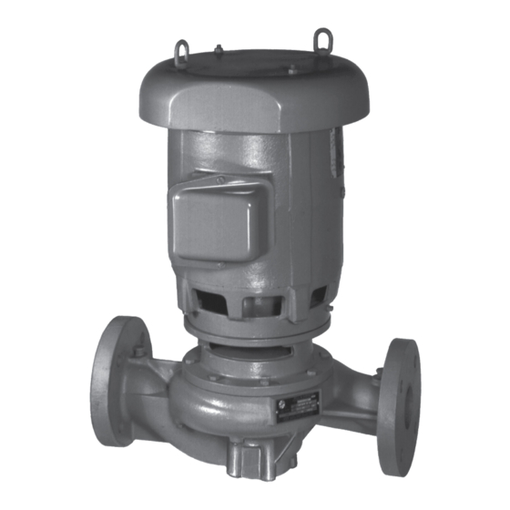
Page 11: Product Description
3 Product Description 3 Product Description 3.1 General description The pump is a centrifugal, in-line, close-coupled pump. These features make the pump easy to install, operate, and service: • High efficiency • Rugged stainless steel-fitted construction • Horizontal or vertical in-line mounting Intended applications WARNING: This product can expose you to chemicals including Lead, which is known to the State of... - Page 12 3 Product Description Seal type/ Standard seal, Optional seal, Optional seal, Optional seal, Optional seal, Packing Parameter BUNA/Carbon/ EPR/Carbon / FKM/Carbon / EPR/Silicon EPR/Carbon / Ceramic Tungsten Ceramic Carbide/Silicon Tungsten Carbide Carbide Carbide with external 1,3,4 flush Maximum 50/50% 50/50% 50/50% 60/40% 50/50%...
-
Page 13: Installation
(See the nameplate on the drive unit to select properly-sized overloads.) NOTICE: Supervision by an authorized Xylem representative is recommended to ensure proper installation. Failure to do so may result in equipment damage or decreased performance. Evaluate the installation in order to determine that the Net Positive Suction Head Available... -
Page 14: Piping Checklist
4 Installation Guideline Explanation/comment Keep the pump as close to the liquid source as practically This minimizes the friction loss and keeps the suction possible. piping as short as possible. If the pump is not on a closed system, locate the pump so that the fewest number of bends or elbows in the suction pipe are needed. -
Page 15: Typical Pump Installation
4 Installation Check Explanation/comment Checked For pumps with flanges, check that the bolt holes in — the pump flanges match the bolt holes in the pipe flanges. For pumps mounted in vertical piping with the motor This prevents strain on the pump parts and in the horizontal position, check that adequate piping. - Page 16 4 Installation In many installations, the piping is installed near the ceiling with the pump located close to the floor for ease of maintenance. Pumps with up to 4 inch nozzles and up to 286 NEMA frame motors can be installed in this configuration with pipe hangers adequate to carry the loads from the pump, piping and piping accessories.
- Page 17 4 Installation Pumps with motors 256 NEMA frame and below can be installed with the shaft horizontal and the piping vertical with supports for the piping (not shown) adequate to carry the loads from the pump and piping. See Figure 8: on page 15 Figure 8 Pumps with motors 256 NEMA frame and below can also...
-
Page 18: Typical System Installation
4 Installation 4.3 Typical system installation 1. Expansion tank 2. B&G Rolairtrol ® air separator 3. Supply to system 4. TPV tank purge system 5. B&G Triple Duty ® valve 6. B&G Series e–80 Pump 7. B&G Suction Diffuser Plus 8. -
Page 19: Commissioning, Startup, Operation, And Shutdown
5 Commissioning, Startup, Operation, and Shutdown 5 Commissioning, Startup, Operation, and Shutdown 5.1 Preparation for startup WARNING: • Failure to follow these precautions before you start the unit will lead to serious personal injury and equipment failure. • Do not operate the pump below the minimum rated flows or with the suction or discharge valves closed. -
Page 20: Prime The Pump
5 Commissioning, Startup, Operation, and Shutdown 5.2 Prime the pump CAUTION: Do not run the pump dry. Make sure that the pump body is full of liquid before startup. If the system does not automatically fill the pump body with liquid, then you must manually prime the pump. 1. -
Page 21: Shut Down The Pump
5 Commissioning, Startup, Operation, and Shutdown Operation at reduced capacity WARNING: Never operate any pumping system with a blocked suction and discharge. Operation, even for a brief period under these conditions, can cause confined pumped fluid to overheat, which results in a violent explosion. You must take all necessary measures to avoid this condition. -
Page 22: Vibration
5 Commissioning, Startup, Operation, and Shutdown 5.7 Vibration After startup, vibration can be measured on the pump bracket at the base of the horizontal (H), vertical (V), and axial (A) directions. The maximum expected value is 0.15 in/sec (3.8 mm/sec) RMS (ANSI/HI 9.6.4) when operating in the Preferred Operating Range (POR) flows from 70% to 120% of the best efficiency point (BEP) (ANSI/HI 9.6.3). -
Page 23: Maintenance
6 Maintenance 6 Maintenance 6.1 Lubrication The pump motor has been lubricated at the factory. Keep the motor properly lubricated in accordance with the motor manufacturer's instructions. 6.2 Disassembly 6.2.1 Disassembly precautions This manual clearly identifies accepted methods for disassembling units. These methods must be adhered to. -
Page 24: Remove The Impeller
When it is necessary to reduce the pump flow rate and generated head by trimming the impeller diameter, the following guidelines apply for stainless steel impellers: • Review the pump hydraulic selection data and consult your local Xylem representative to select the proper reduced diameter. -
Page 25: Pre-Assembly Inspections
6 Maintenance Balancing It is recommended that impellers trimmed more than 5% in diameter be rebalanced per ISO 1940 grade G6.3. Angle cut guidelines Model e-80 5x5x7B pump impellers must be angle cut at reduced diameters according to the following information. ØA ØB Figure 11: 5x5x7B impeller trim —... -
Page 26: Shaft And Sleeve Inspection
6 Maintenance Impeller parts When to replace Vane edges When you see cracks, pitting, or corrosion damage Gaskets, O-rings, and seats replacement • Replace all gaskets and O-rings at each overhaul and disassembly. • Inspect the seats. They must be smooth and free of physical defects. 6.3.2 Shaft and sleeve inspection Inspection criteria Inspect the shaft and sleeve according to this criteria:... -
Page 27: Assemble The Single Mechanical Seal (E-80-S)
6 Maintenance 6.4.2 Assemble the single mechanical seal (e-80-S) 1. Lubricate the shaft sleeve and seal cap with soapy water. Do not use a petroleum lubricant. 2. Insert a stationary seal with an O-ring into the seal cap and slide it onto the shaft. 3. -
Page 28: Assemble The Double Mechanical Seal (E-80-D)
6 Maintenance 6. Attach the seal gland to the coverplate. 7. Tighten the capscrews to the seal gland according to the Capscrew torque table. 1. Seal gland 2. Coverplate 3. For 2 in. seal: 55/64 in. (2.813 cm) 4. Seal locking collar 5. -
Page 29: Assemble The Packed Stuffing Box (E-80-Pf)
6 Maintenance 5. Replace the seal cap gasket. 6. Slide the rotating portion of the seal assembly onto the shaft sleeve. 7. Assemble the coverplate onto the bracket. 8. Tighten the capscrews according to the Capscrew torque values table. 9. Attach the seal cap to the coverplate. 10.Tighten the hex nuts on the seal cap bolts according to the Capscrew torque values table. -
Page 30: Reinstall The Pump Assembly
6 Maintenance 6.4.7 Reinstall the pump assembly 1. Install a new volute gasket. 2. Install the pump assembly into the volute. 3. Tighten the volute capscrews according to the Capscrew torque table. 4. Install a seal flushing tube. 5. Install the drain plug. 6. -
Page 31: Product Warranty
7 Product warranty 7 Product warranty Commercial warranty Warranty. For goods sold to commercial buyers, Seller warrants the goods sold to Buyer hereunder (with the exception of membranes, seals, gaskets, elastomer materials, coatings and other "wear parts" or consumables all of which are not warranted except as otherwise provided in the quotation or sales form) will be (i) be built in accordance with the specifications referred to in the quotation or sales form, if such specifications are expressly made a part of this Agreement, and (ii) free from defects in material and... - Page 32 7 Product warranty Limited consumer warranty Warranty. For goods sold for personal, family or household purposes, Seller warrants the goods purchased hereunder (with the exception of membranes, seals, gaskets, elastomer materials, coatings and other "wear parts" or consumables all of which are not warranted except as otherwise provided in the quotation or sales form) will be free from defects in material and workmanship for a period of one (1) year from the date of installation or eighteen (18) months from the product date code, whichever shall occur first, unless a...
- Page 33 7 Product warranty To make a warranty claim, check first with the dealer from whom you purchased the product or visit www.xyleminc.com for the name and location of the nearest dealer providing warranty service. Series e-80 INSTRUCTION MANUAL...
- Page 36 The original instruction is in English. All non-English instructions are translations of the original instruction. Tel: 1-847-966-3700 Fax: 1-847-965-8379 © 2019 Xylem Inc www.xylem.com/bellgossett Bell & Gossett is a trademark of Xylem Inc or one of its subsidiaries. P2002877_C_en-US_2019-03_Series e-80...
Need help?
Do you have a question about the Bell & Gossett e-80 Series and is the answer not in the manual?
Questions and answers
What are the measurements of the area that the seal is placed for an E-80 2x2x7b ss, 3 hp
The seal area measurement for the Bell & Gossett e-80 Series with a 2-inch seal is 55/64 inches (2.813 cm).
This answer is automatically generated