Xylem Bell & Gossett e-80SCXL Series Instruction Manual
Hide thumbs
Also See for Bell & Gossett e-80SCXL Series:
- Instruction manual (2 pages) ,
- Quick start manual (2 pages)
Table of Contents
Advertisement
Quick Links
Advertisement
Table of Contents

Related Manuals for Xylem Bell & Gossett e-80SCXL Series


Summary of Contents for Xylem Bell & Gossett e-80SCXL Series
- Page 1 INSTRUCTION MANUAL P2005589 A Series e-80SCXL...
-
Page 3: Table Of Contents
Table of Contents Table of Contents 1 Introduction and Safety......................3 1.1 Introduction........................3 1.2 Safety..........................3 1.2.1 Safety terminology and symbols................3 1.2.2 Safety instruction decals..................4 1.2.3 User safety......................5 1.2.4 Protecting the environment..................6 2 Transportation and Storage....................7 2.1 Examine the delivery..................... - Page 4 Table of Contents 6.3.5 Dealer servicing....................27 7 Troubleshooting......................... 28 7.1 Precautions........................28 7.2 The pump unit is turned on but does not work............28 7.3 The differential protection device (RCD) is activated..........28 7.4 The thermal overload protection of the motor is triggered when the pump unit starts..........................28 7.5 The thermal overload protection of the motor is triggered occasionally, or after the pump unit has been running for a few minutes............29...
-
Page 5: Introduction And Safety
This includes any modification to the equipment or use of parts not provided by Xylem. If there is a question regarding the intended use of the equipment, please contact a Xylem representative before proceeding. -
Page 6: Safety Instruction Decals
1 Introduction and Safety Hazard levels Hazard level Indication A hazardous situation which, if not avoided, will DANGER: result in death or serious injury A hazardous situation which, if not avoided, could WARNING: result in death or serious injury A hazardous situation which, if not avoided, could CAUTION: result in minor or moderate injury Notices are used when there is a risk of equipment... -
Page 7: User Safety
1 Introduction and Safety All series e-80SCXL Pumps WARNING ELECTRICAL SHOCK HAZARD. TURN OFF AND LOCKOUT ALL POWER SOURCES PRIOR TO EYEBOLTS OR LIFTING SERVICING PANEL. LUGS IF PROVIDED ARE DO NOT RUN PUMP DRY. FAILURE TO FOLLOW THESE ROTATING COMPONENTS FOR LIFTING ONLY THE SEAL DAMAGE MAY OCCUR. -
Page 8: Protecting The Environment
• Clean-up of spills Exceptional sites CAUTION: Radiation Hazard Do NOT send the product to Xylem if it has been exposed to nuclear radiation, unless Xylem has been informed and appropriate actions have been agreed upon. Recycling guidelines Always follow local laws and regulations regarding recycling. -
Page 9: Transportation And Storage
2 Transportation and Storage 2 Transportation and Storage 2.1 Examine the delivery 2.1.1 Examine the package 1. Examine the package for damaged or missing items upon delivery. 2. Record any damaged or missing items on the receipt and freight bill. 3. -
Page 10: Long-Term Storage
2 Transportation and Storage 2.3 Long-term storage If the unit is stored for more than 6 months, these requirements apply: • Store in a covered and dry location. • Store the unit free from heat, dirt, and vibrations. • Rotate the shaft by hand several times at least every three months. Treat bearing and machined surfaces so that they are well preserved. -
Page 11: Product Description
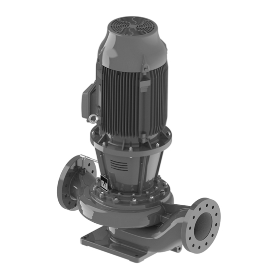
3 Product Description 3 Product Description 3.1 General description The pump is a split coupled pump. These features make the pump easy to install, operate, and service: • High efficiency • Vertical in-line mounting Mechanical seal options The pump has two options for the mechanical seal. Figure 2: Inside mechanical seal Figure 3: Outside mechanical seal Intended applications... -
Page 12: Operational Specifications
3 Product Description NOTICE: • This product is not intended for potable water applications. • This product is non-submersible. For indoor use only. • This product has not been investigated, nor is it intended for, use in swimming pools and marine areas. -
Page 13: Installation
NOTICE: Supervision by an authorized Xylem representative is recommended to ensure proper installation. Failure to do so may result in equipment damage or decreased performance. Evaluate the installation in order to determine that the Net Positive Suction Head Available... -
Page 14: Piping Checklist
4 Installation Guideline Explanation/comment Do not install and operate the equipment in closed Acceptable devices: systems unless the system is constructed with • Pressure relief valves properly-sized safety devices and control devices. • Expansion tanks • Pressure controls • Temperature controls •... -
Page 15: Typical Pump Installation
4 Installation Check Explanation/comment Checked Check that you have a foot valve of equal or Prevent clogging by using a strainer at the greater area than the pump suction piping when suction inlet next to the foot valve. Make you use in an open system with a suction lift. sure that the strainer has an area three times that of the suction pipe with a mesh hole diameter of no less than 0.25 in. -
Page 16: Typical System Installation
4 Installation Figure 6: Piping without suction diffuser, front view Figure 7: Piping without suction diffuser, bottom view 4.3 Typical system installation 1. Expansion tank ® 2. B&G Rolairtrol air separator 3. Supply to system 4. TPV tank purge system ®... -
Page 17: Foundation Requirements
4 Installation 4.4 Foundation requirements Requirements • A substantial foundation and footing should be built to suit local conditions and form a rigid support to maintain alignment. • The foundation must be able to absorb any type of vibration and form a permanent, rigid support for the unit. -
Page 18: Requirements For Setting The Baseplate
4 Installation Anchor bolts • Foundation bolts or anchors of the proper size and type must be used. Foundation bolts that are cast in place can be of either type shown in pump detail figure. Concrete anchors can also be used. The type selected must be consistent with local codes. •... -
Page 19: Level The Base On A Concrete Foundation
4 Installation CAUTION: Equipment Damage. Use an anchor bolt and flat washer at each anchor bolt hole. Otherwise, shifting of the pump unit may occur. Failure to follow these instructions could result in serious property damage and/or moderate personal injury. It is very important that the pump be set level to avoid any mechanical difficulties with the pump. -
Page 20: Commissioning, Startup, Operation, And Shutdown
5 Commissioning, Startup, Operation, and Shutdown 5 Commissioning, Startup, Operation, and Shutdown 5.1 Preparation for startup WARNING: • Failure to follow these precautions before you start the unit will lead to serious personal injury and equipment failure. • Do not operate the pump below the minimum rated flows or with the suction or discharge valves closed. -
Page 21: Prime The Pump
5 Commissioning, Startup, Operation, and Shutdown 5.2 Prime the pump CAUTION: Do not run the pump dry. Make sure that the pump body is full of liquid before startup. If the system does not automatically fill the pump body with liquid, then you must manually prime the pump. 1. -
Page 22: Shut Down The Pump
5 Commissioning, Startup, Operation, and Shutdown Operation at reduced capacity WARNING: Never operate any pumping system with a blocked suction and discharge. Operation, even for a brief period under these conditions, can cause confined pumped fluid to overheat, which results in a violent explosion. You must take all necessary measures to avoid this condition. -
Page 23: Maintenance
6 Maintenance 6 Maintenance 6.1 Lubrication The pump motor has been lubricated at the factory. Keep the motor properly lubricated in accordance with the motor manufacturer's instructions. 6.2 Disassembly 6.2.1 Disassembly precautions This manual clearly identifies accepted methods for disassembling units. These methods must be adhered to. -
Page 24: Reassembly
6 Maintenance • Review the pump hydraulic selection data and consult your local Xylem representative to select the proper reduced diameter. • For machining recommendations, see P2002535 Stainless Steel Impeller Trimming Guidelines. Balancing It is recommended that impellers trimmed more than 5% in diameter be rebalanced per ISO 1940 grade G6.3. - Page 25 6 Maintenance 10, 11 8, 9 Figure 8: Outside seal 1. Seal seat 2. Seal gland 3. Seal seat gasket (seat to cap or gland) 4. Seal seat gasket (seat to cover) 5. Shaft 6. Cover 7. Motor bracket 8. Seal gland cap screws 9.
-
Page 26: Motor Collar Ring Setting
6 Maintenance 11. Reinstall the flush line. 12. Reinstall the coupling guard. 6.3.2 Motor collar ring setting CAUTION: The motor collar ring must be set on the motor shaft at the correct position and set screws torqued to the proper value. The motor collar ring must be set on the motor shaft at a specified distance for both TC motors and IEC motors to insure the pump impeller is in the proper position during pump operation. -
Page 27: Assemble The Coupler
6 Maintenance Distance collar Set screw size (DC) Frame Motor frame size Set screw size in-lbs in (mm) 280S/M 4.744 (120.50) 315S/M/L 5.906 (150) 7.480 (190) 364TC-326TC 4.995 (126.873) 404TC-405TC 6.375 (161.925) NEMA 444TC-449TC 7.625 (193.675) 0.313–24UNF 509LLC 6.395 (162.43) 5011LLC 6.395 (162.43) 6.3.3 Assemble the coupler... -
Page 28: Screw Torque Values
6 Maintenance f. Coupler half g. Coupler half Figure 12: Coupler 8. Insert the coupler cap screws and place a lock washer and nut on each screw. The bolt heads at each level on opposite sides of the coupling should face in different directions for balance. -
Page 29: Dealer Servicing
6 Maintenance 6.3.5 Dealer servicing If trouble occurs that cannot be rectified, contact your local sales and service representative and be prepared to provide this information: 1. Complete nameplate data of pump and motor 2. Suction and discharge pipe pressure gauge readings 3. -
Page 30: Troubleshooting
7 Troubleshooting 7 Troubleshooting 7.1 Precautions WARNING: Maintenance and service must be performed by skilled and qualified personnel only. 7.2 The pump unit is turned on but does not work Cause Remedy Power supply cut off Restore the power supply The thermal overload protection of the motor has Reset the thermal overload protection in the control been triggered... -
Page 31: The Thermal Overload Protection Of The Motor Is Triggered Occasionally, Or After The Pump Unit Has Been Running For A Few Minutes
7 Troubleshooting 7.5 The thermal overload protection of the motor is triggered occasionally, or after the pump unit has been running for a few minutes Cause Remedy It is calibrated at a value too low in relation to the Recalibrate rated current of the motor Input voltage outside the rated limits Make sure the voltage values are correct... -
Page 32: The Pump Starts Up Too Frequently (Automatic Start/Stop)
• Undersized, or • Install an expansion vessel • Not installed Pump unit oversized Contact Xylem or the Authorized Distributor 7.10 The pump unit never stops (automatic start/stop) Cause Remedy The required flow rate s greater than the one... -
Page 33: The Motor Becomes Excessively Hot
7 Troubleshooting Cause Remedy Mechanical seal damaged due to chemical Replace the mechanical seal with one of a make incompatibility with the liquid chemically compatible with the pumped liquid 7.12 The motor becomes excessively hot Cause Remedy Room temperature outside the rated limits Lower the room temperature Cooling fan of the motor clogged or damaged Clean or replace the cooling fan... -
Page 34: Product Warranty
8 Product Warranty 8 Product Warranty Commercial warranty Warranty. For goods sold to commercial buyers, Seller warrants the goods sold to Buyer hereunder (with the exception of membranes, seals, gaskets, elastomer materials, coatings and other "wear parts" or consumables all of which are not warranted except as otherwise provided in the quotation or sales form) will be (i) be built in accordance with the specifications referred to in the quotation or sales form, if such specifications are expressly made a part of this Agreement, and (ii) free from defects in material and workmanship for a... - Page 35 8 Product Warranty materials, coatings and other "wear parts" or consumables all of which are not warranted except as otherwise provided in the quotation or sales form) will be free from defects in material and workmanship for a period of one (1) year from the date of installation or eighteen (18) months from the product date code, whichever shall occur first, unless a longer period is provided by law or is specified in the product documentation (the “Warranty”).
- Page 36 For more information on how Xylem can help you, go to www.xylem.com Xylem Inc. Visit our Web site for the latest version of this document and more information 8200 N.
Need help?
Do you have a question about the Bell & Gossett e-80SCXL Series and is the answer not in the manual?
Questions and answers