Table of Contents
Advertisement
Quick Links
This user's guide describes the characteristics, operation, and use of the ADS9110 Evaluation Module
(EVM) performance demonstration kit (PDK). This kit is an evaluation platform for ADS9110, which is an
18-bit, 2-MSPS, fully-differential input, successive approximation register (SAR) analog-to-digital converter
(ADC) that features an enhanced serial multiSPI
the ADS9110 device with hardware, software, and computer connectivity through the universal serial bus
(USB) interface. This user's guide includes complete circuit descriptions, schematic diagrams, and a bill of
materials.
The following related documents are available through the Texas Instruments web site at www.ti.com.
multiSPI is a registered trademark of Texas Instruments.
Microsoft, Windows are registered trademarks of Microsoft Corporation.
LabVIEW is a trademark of National Instruments.
All other trademarks are the property of their respective owners.
SBAU249 – October 2015
Submit Documentation Feedback
digital interface. The EVM-PDK eases the evaluation of
®
Related Documentation
Device
ADS9110
OPA625
OPA376
OPA378
TPS7A4700
SN74LVC1G08
SN74LVC1G17
TLV3012
Copyright © 2015, Texas Instruments Incorporated
ADS9110EVM-PDK
Literature Number
SBAS629
SBOS688
SBOS406
SBOS417
SBVS204
SCES217
SCES351
SBOS300
User's Guide
SBAU249 – October 2015
1
ADS9110EVM-PDK
Advertisement
Table of Contents

Related Manuals for Texas Instruments ADS9110EVM-PDK


Summary of Contents for Texas Instruments ADS9110EVM-PDK
- Page 1 ADS9110 device with hardware, software, and computer connectivity through the universal serial bus (USB) interface. This user's guide includes complete circuit descriptions, schematic diagrams, and a bill of materials. The following related documents are available through the Texas Instruments web site at www.ti.com. Related Documentation Device...
-
Page 2: Table Of Contents
Schematic Diagram (Page 1) of the ADS9110EVM PCB ............. Schematic Diagram (Page 2) of the ADS9110EVM PCB ............. Schematic Diagram (Page 3) of the ADS9110EVM PCB List of Tables ADS9110EVM-PDK SBAU249 – October 2015 Submit Documentation Feedback Copyright © 2015, Texas Instruments Incorporated... - Page 3 J1 and J2 Configuration per Input Common Mode ............. External Source Requirements for ADS9110 Evaluation ............. External Source Requirements for ADS9110 Evaluation ..................ADS9110EVM Bill of Materials SBAU249 – October 2015 ADS9110EVM-PDK Submit Documentation Feedback Copyright © 2015, Texas Instruments Incorporated...
-
Page 4: Overview
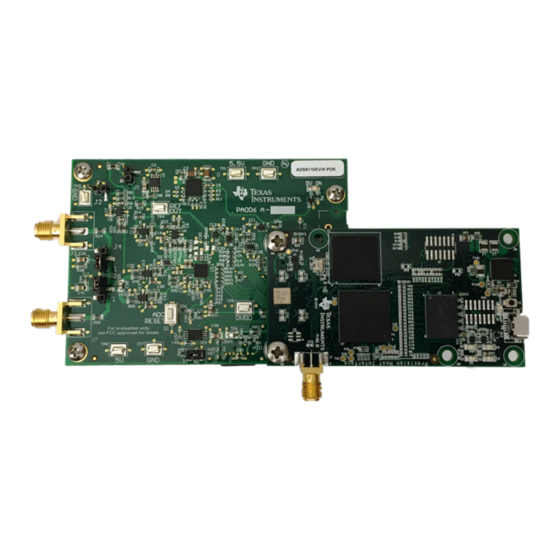
Overview The ADS9110EVM-PDK is a platform for evaluating the performance of the ADS9110 SAR ADC, which is a fully-differential input, 18-bit, 2-MSPS device. The evaluation kit includes the ADS9110EVM board and the Precision Host Interface (PHI) controller board that enables the accompanying computer software to communicate with the ADC over USB for data capture and analysis. -
Page 5: Analog Interface
ADC performance with maximum loading at the full device throughput of 2 MSPS for signal and reference inputs. SBAU249 – October 2015 ADS9110EVM-PDK Submit Documentation Feedback Copyright © 2015, Texas Instruments Incorporated... -
Page 6: Opa625 Differential Input Driving Path
) between 0 Ω and 32 Ω, with 0-V common mode. R must be changed to compensate for larger external source impedance (R ) values or for 2.25-V external source common mode as explained in Section 2.2.3. ADS9110EVM-PDK SBAU249 – October 2015 Submit Documentation Feedback Copyright © 2015, Texas Instruments Incorporated... -
Page 7: Common Mode Selection Jumpers
(R ). The range of values of R for 2.25-V common mode is determined using Equation 177500 270000 1000 1000 SBAU249 – October 2015 ADS9110EVM-PDK Submit Documentation Feedback Copyright © 2015, Texas Instruments Incorporated... -
Page 8: Onboard Adc Reference
C), and the microSD memory card (via the SD/MMC/SDIO bus protocol). The SD card and EEPROM come pre-programmed with the information required to configure and initialize the ADS9110EVM-PDK platform. Once the hardware is initialized, the SD card and EEPROM are no longer used. -
Page 9: Power Supplies
ADS9110EVM-PDK Initial Setup This section explains the initial hardware and software setup procedure that must be completed for the proper operation of the ADS9110EVM-PDK. Default Jumper Settings Jumper settings are determined by common mode and source impedance of the external source that provides a differential signal to the board. -
Page 10: Ads9110 Software Installation Prompts
Figure 4. ADS9110 Software Installation Prompts As a part of the ADS9110 EVM GUI installation, a prompt with a Device Driver Installation will appear on the screen. Click Next to proceed. ADS9110EVM-PDK SBAU249 – October 2015 Submit Documentation Feedback Copyright © 2015, Texas Instruments Incorporated... -
Page 11: Device Driver Installation Wizard Prompts
NOTE: A Notice may appear on the screen stating that Widows can’t verify the publisher of this driver software; Select ‘Install this driver software anyway’. The ADS9110EVM-PDK requires LabVIEW™ Run-Time Engine and may prompt for the installation of this software, if it is not already installed. -
Page 12: Labview Run-Time Engine Installation
ADS9110EVM-PDK Initial Setup www.ti.com Figure 6. LabVIEW Run-Time Engine Installation After these installations, verify that C:\Program Files (x86)\Texas Instruments\ADS9110 EVM is as shown Figure ADS9110EVM-PDK SBAU249 – October 2015 Submit Documentation Feedback Copyright © 2015, Texas Instruments Incorporated... -
Page 13: Ads9110 Evm Folder Post-Installation
ADS9110EVM-PDK Initial Setup www.ti.com Figure 7. ADS9110 EVM Folder Post-Installation SBAU249 – October 2015 ADS9110EVM-PDK Submit Documentation Feedback Copyright © 2015, Texas Instruments Incorporated... -
Page 14: Ads9110Evm-Pdk Operation
ADS9110EVM-PDK Operation www.ti.com ADS9110EVM-PDK Operation The following instructions are a step-by-step guide to connecting the ADS9110EVM-PDK to the computer and evaluating the performance of the ADS9110: 1. Connect the ADS9110EVM to the PHI. Install the two screws as indicated in Figure 2. -
Page 15: Launch The Evm Gui Software
ADS9110EVM-PDK Operation www.ti.com Figure 9. Launch the EVM GUI Software SBAU249 – October 2015 ADS9110EVM-PDK Submit Documentation Feedback Copyright © 2015, Texas Instruments Incorporated... -
Page 16: Evm Gui Global Settings For Adc Control
ADS9110 instantly. “Manual” indicates that the selection made will be made only when the user finalizes his choices and is ready to configure the device. This is described in more detail in the following section. ADS9110EVM-PDK SBAU249 – October 2015 Submit Documentation Feedback Copyright © 2015, Texas Instruments Incorporated... -
Page 17: Register Map Configuration Tool
The impact of changes in the register value reflect on the ADS9110 device on ADS9110EVM-PDK based on the Update Mode selection as described in Section 6.1. -
Page 18: Spectral Analysis Tool
Amplitude for –0.1 dBFS) –3 × 4.45 × 10 ) + 8.9 V S_DIFF Maximum Noise 10 µV Maximum SNR 110 dB Maximum THD –130 dB ADS9110EVM-PDK SBAU249 – October 2015 Submit Documentation Feedback Copyright © 2015, Texas Instruments Incorporated... -
Page 19: Histogram Tool
ADC power supply, and the ADC itself is reflected in the standard deviation of the ADC output code histogram that is obtained by performing multiple conversions of a dc input applied to a given channel. SBAU249 – October 2015 ADS9110EVM-PDK Submit Documentation Feedback Copyright © 2015, Texas Instruments Incorporated... -
Page 20: Histogram Analysis Tool
ADS9110EVM-PDK Operation www.ti.com The histogram corresponding to a dc input is displayed on clicking on the Capture button as shown in Figure Figure 14. Histogram Analysis Tool ADS9110EVM-PDK SBAU249 – October 2015 Submit Documentation Feedback Copyright © 2015, Texas Instruments Incorporated... -
Page 21: Linearity Analysis Tool
NOTE: This analysis can take a couple of minutes to run and it is extremely important that the evaluation board remains undisturbed during the complete duration of the analysis. SBAU249 – October 2015 ADS9110EVM-PDK Submit Documentation Feedback Copyright © 2015, Texas Instruments Incorporated... -
Page 22: Linearity Analysis Tool
ADS9110EVM-PDK Operation www.ti.com Figure 15. Linearity Analysis Tool ADS9110EVM-PDK SBAU249 – October 2015 Submit Documentation Feedback Copyright © 2015, Texas Instruments Incorporated... -
Page 23: Bill Of Materials, Pcb Layout, And Schematics
THT-14-423-10 LBL1 Brady Thermal Transfer Printable Labels, 0.650" W x 0.200" H - 10,000 per roll NX3020NAKW,115 NXP Semiconductor MOSFET, N-CH, 30 V, 0.18 A, SOT-323 SBAU249 – October 2015 ADS9110EVM-PDK Submit Documentation Feedback Copyright © 2015, Texas Instruments Incorporated... - Page 24 SOT23 (DBV0005A), Green (RoHS & no Sb/Br) High-Bandwidth, High-Precision, Low THD+N, 16-Bit and 18-Bit Analog-to-Digital Converter (ADC) Drivers, OPA625IDBVR U6, U12, U13 Texas Instruments DBV0006A SN74LVC1G17DCKR Texas Instruments SINGLE SCHMITT-TRIGGER BUFFER, DCK0005A ADS9110EVM-PDK SBAU249 – October 2015 Submit Documentation Feedback Copyright © 2015, Texas Instruments Incorporated...
- Page 25 RES, 0, 5%, 0.063 W, 0402 ERJ-2GE0R00X Panasonic ERJ-2RKF1002X Panasonic RES, 10.0 k, 1%, 0.1 W, 0402 RC0603FR-071RL Yageo America RES, 1.00, 1%, 0.1 W, 0603 SBAU249 – October 2015 ADS9110EVM-PDK Submit Documentation Feedback Copyright © 2015, Texas Instruments Incorporated...
-
Page 26: Pcb Layout
Bill of Materials, PCB Layout, and Schematics www.ti.com PCB Layout Figure 16 through Figure 19 illustrate the EVM PCB layout. Figure 16. ADS9110EVM PCB Layer 1: Top Layer ADS9110EVM-PDK SBAU249 – October 2015 Submit Documentation Feedback Copyright © 2015, Texas Instruments Incorporated... -
Page 27: Ads9110Evm Pcb Layer 2: Gnd Plane
Bill of Materials, PCB Layout, and Schematics www.ti.com Figure 17. ADS9110EVM PCB Layer 2: GND Plane SBAU249 – October 2015 ADS9110EVM-PDK Submit Documentation Feedback Copyright © 2015, Texas Instruments Incorporated... -
Page 28: Ads9110Evm Pcb Layer 3: Power Planes
Bill of Materials, PCB Layout, and Schematics www.ti.com Figure 18. ADS9110EVM PCB Layer 3: Power Planes ADS9110EVM-PDK SBAU249 – October 2015 Submit Documentation Feedback Copyright © 2015, Texas Instruments Incorporated... -
Page 29: Ads9110Evm Pcb Layer 4: Bottom Layer
Bill of Materials, PCB Layout, and Schematics www.ti.com Figure 19. ADS9110EVM PCB Layer 4: Bottom Layer SBAU249 – October 2015 ADS9110EVM-PDK Submit Documentation Feedback Copyright © 2015, Texas Instruments Incorporated... -
Page 30: Schematic
Number: PA006 Rev: Sheet Title: ADC and Drivers Texas Instruments and/or its licensors do not warra nt the accuracy or completeness of this specificati on or any information contained therein. Texas Inst ruments and/or its licensors do not SVN Rev:... -
Page 31: Schematic Diagram (Page 2) Of The Ads9110Evm Pcb
Number: PA006 Rev: Sheet Title: LDO and Reference Texas Instruments and/or its licensors do not warra nt the accuracy or completeness of this specificati on or any information contained therein. Texas Inst ruments and/or its licensors do not SVN Rev:... -
Page 32: Schematic Diagram (Page 3) Of The Ads9110Evm Pcb
ADS9110EVM-PDK Number: PA006 Rev: Sheet Title: Texas Instruments and/or its licensors do not warra nt the accuracy or completeness of this specificati on or any information contained therein. Texas Inst ruments and/or its licensors do not SVN Rev: Version control disabled... - Page 33 STANDARD TERMS AND CONDITIONS FOR EVALUATION MODULES Delivery: TI delivers TI evaluation boards, kits, or modules, including any accompanying demonstration software, components, or documentation (collectively, an “EVM” or “EVMs”) to the User (“User”) in accordance with the terms and conditions set forth herein. Acceptance of the EVM is expressly subject to the following terms and conditions.
- Page 34 FCC Interference Statement for Class B EVM devices NOTE: This equipment has been tested and found to comply with the limits for a Class B digital device, pursuant to part 15 of the FCC Rules. These limits are designed to provide reasonable protection against harmful interference in a residential installation.
- Page 35 【無線電波を送信する製品の開発キットをお使いになる際の注意事項】 本開発キットは技術基準適合証明を受けておりません。 本製品のご使用に際しては、電波法遵守のため、以下のいずれかの措置を取っていただく必要がありますのでご注意ください。 1. 電波法施行規則第6条第1項第1号に基づく平成18年3月28日総務省告示第173号で定められた電波暗室等の試験設備でご使用 いただく。 2. 実験局の免許を取得後ご使用いただく。 3. 技術基準適合証明を取得後ご使用いただく。 なお、本製品は、上記の「ご使用にあたっての注意」を譲渡先、移転先に通知しない限り、譲渡、移転できないものとします。 上記を遵守頂けない場合は、電波法の罰則が適用される可能性があることをご留意ください。 日本テキサス・インスツルメンツ株式会社 東京都新宿区西新宿6丁目24番1号 西新宿三井ビル 3.3.3 Notice for EVMs for Power Line Communication: Please see http://www.tij.co.jp/lsds/ti_ja/general/eStore/notice_02.page 電力線搬送波通信についての開発キットをお使いになる際の注意事項については、次のところをご覧くださ い。http://www.tij.co.jp/lsds/ti_ja/general/eStore/notice_02.page SPACER EVM Use Restrictions and Warnings: 4.1 EVMS ARE NOT FOR USE IN FUNCTIONAL SAFETY AND/OR SAFETY CRITICAL EVALUATIONS, INCLUDING BUT NOT LIMITED TO EVALUATIONS OF LIFE SUPPORT APPLICATIONS.
- Page 36 Notwithstanding the foregoing, any judgment may be enforced in any United States or foreign court, and TI may seek injunctive relief in any United States or foreign court. Mailing Address: Texas Instruments, Post Office Box 655303, Dallas, Texas 75265 Copyright © 2015, Texas Instruments Incorporated...
- Page 37 IMPORTANT NOTICE Texas Instruments Incorporated and its subsidiaries (TI) reserve the right to make corrections, enhancements, improvements and other changes to its semiconductor products and services per JESD46, latest issue, and to discontinue any product or service per JESD48, latest issue.
Need help?
Do you have a question about the ADS9110EVM-PDK and is the answer not in the manual?
Questions and answers