Table of Contents
Advertisement
Quick Links
This user's guide describes the characteristics, operation, and use of the ADS9224R evaluation module
(EVM) performance demonstration kit (PDK). The EVM-PDK eases the evaluation of the
device with hardware, software, and computer connectivity through a universal serial bus (USB) interface.
Throughout this document, the terms evaluation board, evaluation module, and EVM are synonymous with
the ADS9224REVM-PDK. This user's guide includes complete circuit descriptions, schematic diagrams,
and a bill of materials.
The following related documents are available through the Texas Instruments web site at www.ti.com.
SBAU315A – July 2018 – Revised June 2019
Submit Documentation Feedback
Related Documentation
Device
ADS9224R
THS4551
REF5025
TPS7A4700
Copyright © 2018–2019, Texas Instruments Incorporated
SBAU315A – July 2018 – Revised June 2019
ADS9224REVM-PDK
Literature Number
SBAS876
SBOS778
SBOS410
SBVS204
User's Guide
ADS9224R
1
ADS9224REVM-PDK
Advertisement
Table of Contents

Subscribe to Our Youtube Channel
Related Manuals for Texas Instruments ADS9224REVM-PDK


Summary of Contents for Texas Instruments ADS9224REVM-PDK
-
Page 1: Ads9224Revm Schematic Diagram
Throughout this document, the terms evaluation board, evaluation module, and EVM are synonymous with the ADS9224REVM-PDK. This user's guide includes complete circuit descriptions, schematic diagrams, and a bill of materials. The following related documents are available through the Texas Instruments web site at www.ti.com. Related Documentation Device... -
Page 2: Table Of Contents
.................. ADS9224REVM Schematic Diagram 2 List of Tables ................J2 to J5 SMA Analog Interface Connections ................... JP1 to JP4 Header Descriptions ADS9224REVM-PDK SBAU315A – July 2018 – Revised June 2019 Submit Documentation Feedback Copyright © 2018–2019, Texas Instruments Incorporated... - Page 3 External Source Requirements for Evaluation of the ADS9224R ..................ADS9224REVM Bill of Materials Trademarks multiSPI is a trademark of Texas Instruments. Windows is a registered trademark of Microsoft Corporation. LabVIEW is a trademark of National Instruments. All other trademarks are the property of their respective owners.
-
Page 4: Overview
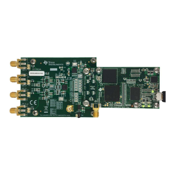
Overview www.ti.com Overview The ADS9224REVM-PDK is an evaluation platform for the ADS9224R, a dual, simultaneous-sampling, 16- bit, 3-MSPS, fully-differential input successive approximation register (SAR) analog-to-digital converter (ADC). The ADS9224R features an enhanced serial multiSPI™ digital interface. The evaluation kit includes the ADS9224REVM board and the Precision Host Interface (PHI) controller board that enables the accompanying computer software to communicate with the ADC using a USB interface for data capture and analysis. -
Page 5: Analog Interface
Thus, the evaluation board provides the THS4551 FDA driver that maintains ADC performance with maximum loading at the full device throughput of 3 MSPS. SBAU315A – July 2018 – Revised June 2019 ADS9224REVM-PDK Submit Documentation Feedback Copyright © 2018–2019, Texas Instruments Incorporated... -
Page 6: Ths4551 Differential Input Driving Path
A0(+) 4.32 AINN -1.828 V 3.876 V 100 pF FSR_ADC 2.048 V ±V 0.22 V ±4.096V Figure 2. THS4551 Fully-Differential Amplifier Driver ADS9224REVM-PDK SBAU315A – July 2018 – Revised June 2019 Submit Documentation Feedback Copyright © 2018–2019, Texas Instruments Incorporated... -
Page 7: Ads9224R Internal Reference
ADS9224R ADC (over SPI or multiSPI) and the EEPROM (over I C). The EEPROM comes preprogrammed with the information required to configure and initialize the ADS9224REVM-PDK platform. After the hardware is initialized, the EEPROM is no longer used. multiSPI™ for ADC Digital IO... -
Page 8: Power Supplies
5.5-V supply from PHI EVM controller TP19 5-V analog supply TP20 DVDD 3.3-V digital supply TP21 VS– Negative supply for fully-differential input amplifiers ADS9224REVM-PDK SBAU315A – July 2018 – Revised June 2019 Submit Documentation Feedback Copyright © 2018–2019, Texas Instruments Incorporated... -
Page 9: Setup
Section 2.1. Figure 3 shows the default factory jumper locations and settings. Figure 3. ADS9224REVM-PDK Jumper Locations Table 5 explains the functionality of each of these jumpers and their default configurations. Table 5. Default Jumper Configurations Designator... -
Page 10: Evm Graphical User Interface (Gui) Software Installation
As a part of the ADS9224REVM GUI installation, a prompt with a Device Driver Installation will appear on the screen. Click Next to proceed. Figure 5. Device Driver Installation Wizard Prompts ADS9224REVM-PDK SBAU315A – July 2018 – Revised June 2019 Submit Documentation Feedback Copyright © 2018–2019, Texas Instruments Incorporated... -
Page 11: Labview Run-Time Engine Installation
The ADS9224xEVM-PDK requires LabVIEW™ Run-Time Engine, and may prompt for the installation of this software if not already installed. Figure 6. LabVIEW Run-Time Engine Installation SBAU315A – July 2018 – Revised June 2019 ADS9224REVM-PDK Submit Documentation Feedback Copyright © 2018–2019, Texas Instruments Incorporated... -
Page 12: Ads9224Revm-Pdk Folder Post-Installation
Setup www.ti.com After these installations, verify that C:\Program Files (x86)\Texas Instruments\ADS9224REVM is as shown Figure Figure 7. ADS9224REVM-PDK Folder Post-Installation ADS9224REVM-PDK SBAU315A – July 2018 – Revised June 2019 Submit Documentation Feedback Copyright © 2018–2019, Texas Instruments Incorporated... -
Page 13: Operation
Operation www.ti.com Operation The following instructions are a step-by-step guide to connecting the ADS9224REVM-PDK to the computer and evaluating the performance of the ADS9224R: 1. Connect the ADS9224REVM to the PHI, and install the two screws, as indicated in Figure 2. -
Page 14: Evm Gui Global Settings For Adc Control
The SDO Mode drop-down menu allows selection between standard SPI and multiSPI modes. The ADS9224REVM-PDK software supports maximum throughput of 3-MSPS when using Dual- and Quad- SDO lanes, and a maximum throughput of 2.61-MSPS when using Single-SDO lane. For maximum throughput of 3-MSPS, select the Dual or Quad-SDO lanes. -
Page 15: Register Map Configuration Tool
If interface mode settings are affected by the change in register values, this change reflects on the left pane immediately. The effect of changes in the register value reflect on the ADS9224R device on ADS9224REVM-PDK based on the Update Mode selection, as described in Figure Figure 11. -
Page 16: Time Domain Display Tool
Figure 12. Time Domain Display Tool Options ADS9224REVM-PDK SBAU315A – July 2018 – Revised June 2019 Submit Documentation Feedback Copyright © 2018–2019, Texas Instruments Incorporated... -
Page 17: Spectral Analysis Tool
For 2-kHz SNR and ENOB evaluation at a maximum throughput of 3 MSPS, the number of samples must be a minimum of 65536. Figure 13. Spectral Analysis Tool SBAU315A – July 2018 – Revised June 2019 ADS9224REVM-PDK Submit Documentation Feedback Copyright © 2018–2019, Texas Instruments Incorporated... -
Page 18: Histogram Tool
The histogram corresponding to a dc input is displayed on clicking the Capture button, as shown in Figure Figure 14. Histogram Analysis Tool ADS9224REVM-PDK SBAU315A – July 2018 – Revised June 2019 Submit Documentation Feedback Copyright © 2018–2019, Texas Instruments Incorporated... -
Page 19: Ads9224Revm Bill Of Materials, Pcb Layout, And Schematics
Machine H1, H2, H3, H4 4 MACHINE SCREW PAN PHILLIPS 4-40 Screw, 4-40, PMSSS 440 0025 PH B&F Fastener Supply 1/4 inch SBAU315A – July 2018 – Revised June 2019 ADS9224REVM-PDK Submit Documentation Feedback Copyright © 2018–2019, Texas Instruments Incorporated... - Page 20 RES, 100, 1%, 0.1 W, 0603 0603 RC0603FR-07100RL Yageo America R9, R11, R43, 10.0 RES, 10.0, 0.1%, 0.1 W, 0603 0603 TNPW060310R0BEEA Vishay-Dale ADS9224REVM-PDK SBAU315A – July 2018 – Revised June 2019 Submit Documentation Feedback Copyright © 2018–2019, Texas Instruments Incorporated...
- Page 21 CAP, CERM, 1 uF, 10 V, +/- 10%, X7R, 0805 0805 0805ZC105KAT2A 10uF CAP, CERM, 10 uF, 16 V, +/- 10%, X7R, 0805 0805 CL21B106KOQNNNE Samsung Electro-Mechanics SBAU315A – July 2018 – Revised June 2019 ADS9224REVM-PDK Submit Documentation Feedback Copyright © 2018–2019, Texas Instruments Incorporated...
- Page 22 RES, 0, 1%, 0.1 W, AEC-Q200 Grade 0, 0603 0603 RMCF0603ZT0R00 Stackpole Electronics Inc 3 µVpp/V Noise, 3 ppm/°C Drift Precision Series DGK0008A REF5025AIDGKR Texas Instruments Voltage Reference, DGK0008A (VSSOP-8) ADS9224REVM-PDK SBAU315A – July 2018 – Revised June 2019 Submit Documentation Feedback Copyright © 2018–2019, Texas Instruments Incorporated...
-
Page 23: Pcb Layout
Figure 19 illustrate the EVM PCB layout. Figure 15. ADS9224REVM PCB Top Overlay Figure 16. ADS9224REVM PCB Layer 1: Top Layer SBAU315A – July 2018 – Revised June 2019 ADS9224REVM-PDK Submit Documentation Feedback Copyright © 2018–2019, Texas Instruments Incorporated... -
Page 24: Ads9224Revm Pcb Layer 2: Gnd Plane
ADS9224REVM Bill of Materials, PCB Layout, and Schematics www.ti.com Figure 17. ADS9224REVM PCB Layer 2: GND Plane Figure 18. ADS9224REVM PCB Layer 3: Power Planes ADS9224REVM-PDK SBAU315A – July 2018 – Revised June 2019 Submit Documentation Feedback Copyright © 2018–2019, Texas Instruments Incorporated... -
Page 25: Ads9224Revm Pcb Layer 4: Bottom Layer
ADS9224REVM Bill of Materials, PCB Layout, and Schematics www.ti.com Figure 19. ADS9224REVM PCB Layer 4: Bottom Layer SBAU315A – July 2018 – Revised June 2019 ADS9224REVM-PDK Submit Documentation Feedback Copyright © 2018–2019, Texas Instruments Incorporated... -
Page 26: Schematics
V- pin 5 on U3 DVDD 100k REFP/2 VICM_2 SN74LVC1G14DCKT 0.1uF 0.01uF 0.1uF 0.01uF 1µF 0.1uF 0.1uF 100k Figure 20. ADS9224REVM Schematic Diagram 1 ADS9224REVM-PDK SBAU315A – July 2018 – Revised June 2019 Submit Documentation Feedback Copyright © 2018–2019, Texas Instruments Incorporated... -
Page 27: Ads9224Revm Schematic Diagram 2
1N4148WT 10.0k EVM_ID_SCL 1N4148WT EVM_ID_SDA 0.1uF BR24G32FVT-3AGE2 Origins pg 1, conn J1 FDA NEGATIVE SUPPLY TP21 Figure 21. ADS9224REVM Schematic Diagram 2 SBAU315A – July 2018 – Revised June 2019 ADS9224REVM-PDK Submit Documentation Feedback Copyright © 2018–2019, Texas Instruments Incorporated... - Page 28 Changed signal frequency and source differential signal specification values in External Source Requirements for ....................Evaluation of the ADS9224R table ..................• Changed ADS9224EVM Bill of Materials table ......................• Changed Schematics figures Revision History SBAU315A – July 2018 – Revised June 2019 Submit Documentation Feedback Copyright © 2018–2019, Texas Instruments Incorporated...
- Page 29 STANDARD TERMS FOR EVALUATION MODULES Delivery: TI delivers TI evaluation boards, kits, or modules, including any accompanying demonstration software, components, and/or documentation which may be provided together or separately (collectively, an “EVM” or “EVMs”) to the User (“User”) in accordance with the terms set forth herein.
- Page 30 www.ti.com Regulatory Notices: 3.1 United States 3.1.1 Notice applicable to EVMs not FCC-Approved: FCC NOTICE: This kit is designed to allow product developers to evaluate electronic components, circuitry, or software associated with the kit to determine whether to incorporate such items in a finished product and software developers to write software applications for use with the end product.
- Page 31 www.ti.com Concernant les EVMs avec antennes détachables Conformément à la réglementation d'Industrie Canada, le présent émetteur radio peut fonctionner avec une antenne d'un type et d'un gain maximal (ou inférieur) approuvé pour l'émetteur par Industrie Canada. Dans le but de réduire les risques de brouillage radioélectrique à...
- Page 32 www.ti.com EVM Use Restrictions and Warnings: 4.1 EVMS ARE NOT FOR USE IN FUNCTIONAL SAFETY AND/OR SAFETY CRITICAL EVALUATIONS, INCLUDING BUT NOT LIMITED TO EVALUATIONS OF LIFE SUPPORT APPLICATIONS. 4.2 User must read and apply the user guide and other available documentation provided by TI regarding the EVM prior to handling or using the EVM, including without limitation any warning or restriction notices.
- Page 33 Notwithstanding the foregoing, any judgment may be enforced in any United States or foreign court, and TI may seek injunctive relief in any United States or foreign court. Mailing Address: Texas Instruments, Post Office Box 655303, Dallas, Texas 75265 Copyright © 2019, Texas Instruments Incorporated...
- Page 34 TI products. TI’s provision of these resources does not expand or otherwise alter TI’s applicable warranties or warranty disclaimers for TI products. Mailing Address: Texas Instruments, Post Office Box 655303, Dallas, Texas 75265 Copyright © 2019, Texas Instruments Incorporated...
Need help?
Do you have a question about the ADS9224REVM-PDK and is the answer not in the manual?
Questions and answers