Table of Contents
Advertisement
Quick Links
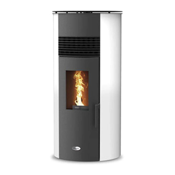
K500
Wood Pellet Stoves
INSTALLATION AND OPERATING INSTRUCTIONS
This appliance is hot while in operation and retains its heat for a long period of time after use.
Children, aged or infirm persons should be supervised at all times and should not be allowed to touch
the hot working surfaces while in use or until the appliance has thoroughly cooled.
When using the stove in situations where children, aged and/or infirm persons are present a fireguard
must be used to prevent accidental contact with the stove. The fireguard should be manufactured in
BS 8423:2002.
accordance with
Advertisement
Table of Contents

Subscribe to Our Youtube Channel
Related Manuals for Stanley K500


Summary of Contents for Stanley K500
- Page 1 K500 Wood Pellet Stoves INSTALLATION AND OPERATING INSTRUCTIONS This appliance is hot while in operation and retains its heat for a long period of time after use. Children, aged or infirm persons should be supervised at all times and should not be allowed to touch the hot working surfaces while in use or until the appliance has thoroughly cooled.
-
Page 2: Table Of Contents
Stanley Pellet Stove Warranty ........ -
Page 3: Setting The Language
CONDITIONS OF WARRANTY Your Stanley pellet stove is guaranteed against any part that fails (under normal operating conditions) as detailed in the following table with timelines specified from the date of installation of the appliance. If the unit is not installed within six months of date of purchase, the warranty will commence six months from the date of purchase. -
Page 4: Important Operation/ Maintenance Notes
Do not burn fuel with a high moisture content, ie damp pellets. Do not tamper with the safety devices or adjustment features without prior authorization from Waterford Stanley During the first firings it is recommended to ventilate the room as an unpleasant (not toxic) odour may be emit- ted as the paint is completing curement. -
Page 5: Installation Checklist
INSTALLATION CHECKLIST Flue System 1. Minimum Flue Height of 2 metres. 2. Tee piece fitted at base of flue. 3. Appliance should be connected using an 80mm connecting flue pipe, increasing to 125mm within 1.5 metres of the appliance 4. Horizontal run of connecting pipe must not exceed 600mm. 5. -
Page 6: Technical Specifications
TECHNICAL SPECIFICATIONS... -
Page 7: Unpacking
Contents The package of this unit contains: Free Standing Pellet Stove K500 Instruction manual Power cable; Infrared remote control; Cleaning bar handle; Fig. 2 Unpacking the Unit To unpack the equipment, you must first Installation Requirements remove the retractable bag that surrounds the Location, Suitable area to be heated. -
Page 8: Flue/ Chimney Installation
45 authorised Stanley service agent. degrees. Clearances to combustibles The flue termination point/outlet must be above roof... -
Page 9: Ventilation & Combustion Air Requirements
A clearance to combustible of 50cm must be External Air Connection maintained to either side of the stove , 30 cm To connect the stove to outside air an outside to the rear and 150 cm to the front of the stove air kit and an offset adaptor can be supplied as see Fig 6 an optional extra. -
Page 10: Using The Pellet Stove
Using the Pellet Stove The stove has a probe for measuring the room Before starting up the unit, please check the temperature. This probe is attached to the grid following: on the rear panel For a good reading of the Ensure the unit is properly connected to the room temperature, avoid the contact between power mains using the 230V AC power cable. -
Page 11: Selecting Manual Or Automatic Mode
Fig. 13 Button Function Mode/ Esc Toggle between manual and automatic mode / escape or exit menus . Menu / OK when flashing Access menus / ok -accept value On / OFF Start unit when it is off , stop unit when it is on, Resets error messages Minus sign “-”... -
Page 12: Setting Time And Date
Setting the Date and Time Press "+" to scroll to the next menu. The “Day number” is displayed. This is the date / day of Setting the date: the month. press the Menu key twice until “Day and Time Fig. 19 is displayed. -
Page 13: Setting The Programmer
Press “set”; the display starts to flash. Press Setting the Programmer. the “+” or “-“ key to select the desired pro- The unit is equipped with a timer that allows gramme and then press “ok” to confirm. Press the unit to be turned on or off at specified the "+"... - Page 14 To set the operating power level (1 to 5) of Fig. 28 Programme P1, press “Set”. The display starts to flash. Press the “+” or “-" key to select the desired power level (1 to 5), and then “Ok” to confirm.
-
Page 15: User Information
User Information Once the pre-set time is elapsed, the unit To access the user information. shuts down. At the start of the Shutdown press “set” twice and then press “+” until phase, another timer for a different pre-set “ User Info is displayed” period of time is triggered (Start-up delay time: press set to acess the “User info”... -
Page 16: Combustion Settings
Combustion settings. Shut down. This allows for adjustment of the “pellet” quan- To turn off the pellet stove is carried out by tity and the “air flow” pressing the ON / OFF button for 3 seconds. The display will show “shut down” until full Pellet completion of this phase. -
Page 17: Installing The Casings
This manual describes how to install the casings for the K500 unit. To assemble the casings the Installer must have screwdriver with screw tip. - Page 18 Fig. 39 Fig. 41 Fig. 40 To fit the side panels it is necessary to remove Place the covers on to the stove so that the the door from the stove, to remove the door, screw on the back of the unit pass through the open the door first , lift the door to allow the bot- wide part of the key shaped slot, slide the panel tom pin to disengage, move the door slightly to...
- Page 19 Fig. 49 Note, There is an optional additional blower kit available to be fitted to allow the K500 provide warm air to additional rooms using up to 7 metres of diameter 100mm pipe. Full assembly isnstuction is provided with the kit.
-
Page 20: Maintenance / Glass Cleaning
Pellet Reservoir / Hopper Glass Cleaning The glass can only be cleaned when it is com- To access the pellet reservoir, open the lid on pletely cold. It must be cleaned with a suitable the top of the unit by pushing down and sliding product in accordance with the instructions for the clip top the left. -
Page 21: Weekly Maintenance/Cleaninfg The Flueways
Weekly Maintenance/Cleaning the flueways. Fig. 59 For weekly cleaning, pull and push the clean- ing bar to clean the heat excchanger, open the door remove the burner and clean the ashes from inside the combustion chamber. Also, clean the ashes inside the burner to ensure that the burner holes are completely unob- structed. -
Page 22: Additional Cleaning
Additional cleaning for each 600-800 Kg of The exhaust fan should be cleaned at least, pellets consumed. once a year and on additional ocassions if you notice that the fume extraction is not effective, Remove the side covers to access the access we recommend cleaning the interior of the covers of the combustion chamber. -
Page 23: Maintenance Plan And Log
Note A “service” warning on the display (mainte- nance due) indicates that the unit has exceed- ed 2100 operating hours. In this case, the client must perform the unit's maintenance pro- cedure (following the instruction on the Technical Manual). Once this procedure is completed the hour meter may be reset, to clear the waning message. - Page 24 Troubleshooting guide Note When triggered, all the alarms below cause the machine to shutdown. The alarm must be reset and the unit restarted. To reset the unit, press the “On/Off” button for 10 seconds until the alarm sounds.
-
Page 25: Troubleshooting
Exploded view. -
Page 26: Spare Parts List
Flueway access plate CO0317000000030 On-Off Switch- Filter CO0315000000060 Pressure switch support CO0315000000030 Pressure Switch CO0312000000009 Encoder board IC0490000000004 Extractor fan k100 PA1090G031 K500 Ventilation Kit CO0713001006501 Levelling bolt IC0120000260024 Trap door IC0402000030006 Ash Pan IS0703030000007 Ash Grill IC0420000260076 Steel Door IS1013200000011... -
Page 27: Ignition Logic Flow Diagram
Ignition logic flow diagram... -
Page 28: Shut Down Logic Flow Diagram
Shut down logic flow diagram Fixed timer program schedules Manufactured by Waterford Stanley Ltd., Unit 401-403, IDA Industrial Estate, Cork Road, Waterford, Ireland. Tel: (051) 302300 NH 190320 Rev 001...
Need help?
Do you have a question about the K500 and is the answer not in the manual?
Questions and answers