Table of Contents
Advertisement
Quick Links
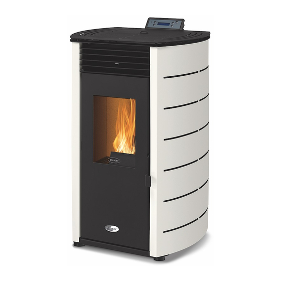
K100 & K300
Wood Pellet Stoves
INSTALLATION AND OPERATING INSTRUCTIONS
This appliance is hot while in operation and retains its heat for a long period of time after use.
Children, aged or infirm persons should be supervised at all times and should not be allowed to touch
the hot working surfaces while in use or until the appliance has thoroughly cooled.
When using the stove in situations where children, aged and/or infirm persons are present a fireguard
must be used to prevent accidental contact with the stove. The fireguard should be manufactured in
BS 8423:2002.
accordance with
Advertisement
Table of Contents

Related Manuals for Stanley SOLIS K100


Summary of Contents for Stanley SOLIS K100
- Page 1 K100 & K300 Wood Pellet Stoves INSTALLATION AND OPERATING INSTRUCTIONS This appliance is hot while in operation and retains its heat for a long period of time after use. Children, aged or infirm persons should be supervised at all times and should not be allowed to touch the hot working surfaces while in use or until the appliance has thoroughly cooled.
-
Page 2: Table Of Contents
Stanley Pellet Stove Warranty ........ -
Page 3: Setting The Language
CONDITIONS OF WARRANTY Your Stanley pellet stove is guaranteed against any part that fails (under normal operating conditions) as detailed in the following table with timelines specified from the date of installation of the appliance. If the unit is not installed within six months of date of purchase, the warranty will commence six months from the date of purchase. -
Page 4: Important Operation/ Maintenance Notes
Do not burn fuel with a high moisture content, ie damp pellets. Do not tamper with the safety devices or adjustment features without prior authorization from Waterford Stanley During the first firings it is recommended to ventilate the room as an unpleasant (not toxic) odour may be emit- ted as the paint is completing curement. -
Page 5: Installation Checklist
INSTALLATION CHECKLIST Flue System 1. Minimum Flue Height of 2 metres. 2. Tee piece fitted at base of flue. 3. Appliance should be connected using an 80mm connecting flue pipe, increasing to 125mm within 1.5 metres of the appliance 4. Horizontal run of connecting pipe must not exceed 600mm. 5. -
Page 6: Technical Specifications
Technical Specifications Parameters K100 K300 Units Height Width Depth Weight Diameter of the fume discharge pipe Hopper capacity Maximum heating capacity m³ Maximum heat output Minimum heat output Minimum fuel consumption kg / h Maximum fuel consumption kg / h Rated electrical current Electric power at start-up (<10 min.) Rated voltage... - Page 7 K300 K100 Models with curved side panels W = 560 Models with flat side panels W = 495...
-
Page 8: Contents -Unpacking- Installation Requirements
Contents The package of this unit contains: Free Standing Pellet Stove K100, or K300 Instruction manual Power cable; Infrared remote control; Cleaning bar handle; Covers according to selected model. Unpacking the Unit To unpack the equipment, you must first Installation Requirements remove the retractable bag that surrounds the Location, Suitable area to be heated. -
Page 9: Chimney Installation- Electrical Connection
45 authorised Stanley service agent. degrees. The flue termination point/outlet must be above roof level and in accordance with building regulations part J. -
Page 10: Clearance To Combustibles
Clearances to combustibles In the event that the product is installed in a non combustible recess, clearances for ser- A clearance to combustibles of 100cm must be vicing,must be provided, 200mm to the rear maintained above the stove see Fig 5 and 300mm to the sides. -
Page 11: Using The Pellet Stove
Remote Control Using the Pellet Stove The remote control allows you to switch the Before starting up the unit, please check the stove on and off and change the power following: level of the appliance (the stove cannot be in Ensure the unit is properly connected to the automatic mode). -
Page 12: Control And Display Panel
Control and Display Panel When first connected the display indicates the "OFF" status of the stove, it can also indicate the chrono activation, system errors, selected combustion power, selected ventilation power, current room temperature and selected room temperature set-point. While in the Home Page by pressing the key: “P1”... -
Page 13: Settings Menu- Language- Time And Date
Settings Menu By pressing the P3 key for 3 seconds, you will display the Settings, Service, Display System Menu In the Date and Time menu, select Time, with the P4 and P6 keys, and press the P3 key, the time will appear in editable mode, flashing, with P4 and P6 select the correct time and press P3 to validate. -
Page 14: Setiing Remote Control & Display
To edit the Month, you must use the P4 and P6 keys to select this information and then P3, the month will appear in editable mode, with P4 and P6 select the desired month and then press P3 again to validate. With the P4 and P6 keys you can activate or deactivate the Remote Control, pressing P3 to validate the option. -
Page 15: Service Menu
Screen Saver The following functions are available in this In the Display menu with P4 and P6 select the menu. Screen Saver function by pressing on the P3 key. In this function you can activate or deactivate the screen lock. To return to the Display menu, press P1. - Page 16 Error List It is possible to query the exhaust temperature, In the Service menu with P4 and P6 select the ambient temperature and the status of submenu Error list, pressing the P3 key the inputs. Whether the input status is open (0) to validate.
-
Page 17: Auger Calibration - Fan Calibration
Auger Calibration In the Service menu with P4 and P6 select the Auger Calibration submenu, pressing the P3 key to validate. Manual Load Using P4 and P6 select the Manual Load sub- menu, pressing theP3 key to validate. In this submenu with the keys P4 and P6 you can adjust the quantity of pellet to be fed, between -7 (-14%) and 7 (+14%). -
Page 18: Power Menu
Power Menu Heating Press the P3 key to access the following With P4 and P6 you must select Heating and menus, Power, Thermostats and Chrono. Use then press P3 to validate access to this the P4 and P6 keys to select the required submenu.( This controls the speed of the menu and then press P3 to confirm the heationg circulation fan) -
Page 19: Thermostats Menu
This submenu allows you to modify the power In this menu, select the submenu Room, using value of the canalization fan. It is only the P3 key. displayed if you select a heating system that includes a second heating fan. With the P4 and P6 keys it can be set in automatic or manual mode: in the second case, the user selects the power from 0 to 5. - Page 20 You must then enter the Programme submenu, You must press P3 and this option will be in using the P6 key to select and P3 to editable mode, flashing. Press P4 and P6 to validate the choice. select the desired time and then use the P3 key to save.
- Page 21 You must press P3 and this option will be in editable mode, flashing. Press P4 and P6 to select the desired time and then use the P3 key to save. Repeat this process for the time at which the unit is to shut down, using P4 and P6.
-
Page 22: Info Menu
Info Menu In this menu the user can view some informa- tion about the device, such as measured values and aspects relating to the electronics. In the initial menu, press the P5 key once, and the menu will appear. With the P4 and P6 keys you can scroll through the different variables. -
Page 23: Faultfinding
Alarm / Fault Finding Sond – Probe’s anomaly during the control in Check Up. Ignition Block – The message appears if the system has been is turned off during Ignition (after Preload) by an external device: the system will stop only when it goes in Run Mode. -
Page 24: Troubleshooting
Alarm Code Troubleshooting Pellet drum Er01 110 °C, even with - Room fan not working - call for temperature is service too high equipment OFF - Thermostat defective - call for service - Ventilation defective Pressure regu- Er02 Door open, draught - Close door and remove faulty lator pressure switch... - Page 25 Alarm Code Troubleshooting Lack of voltage Er15 Lack of voltage - Check supply voltage with your supply supply electricity supplier for more than 50 min - Check the simultaneous use of electrical appliances - In the event of a short power failure (<10s) the stove continues to operate normally - If the system was in the ON state...
-
Page 26: Operation
Operation. Fig 10 shows the baffle position as viewed from inside the firebox. Item 1 on the picture After loading the pellets into the hopper, press highlights that the tab on the baffle must over- and hold the ON/OFF lap down over the vermiculite lining at the rear button for 3s, to start the stove. -
Page 27: Side Panel Assembly Insturctions
Assembly Instruction for Installing the control panel, side panels , hopper cover and grill. Note Installing the Casings on K100. When installing the display handle it with care Before installing the casings you should check because there is a cable from the central unit immediately whether the packing is complete of the stove connected to it. - Page 28 Secure the side panels to the back of the unit using 10 screws from the kit, as shown in Fig. 15 Figure 18. Fig. 16 Fig. 18 The cover is equipped with four guide pins (1) in the bottom to ensure its proper placement. These guide pins must be fitted onto the springs in located in the structure.
- Page 29 Fit the top plate as shown in figure 21. Installing the Casings on K300. To ensure that the top is properly seated, it Before installing the casings you should check contains four pins on the bottom that should fit immediately whether the packing is complete the springs in the frame.
- Page 30 Fasten the upper part of the grill with two self tapping screws location C, fixed directly to the Fig. 26 cover previously placed. Then fix with M5x12 screws at locations marked A and fix with M5x12 screws and M5 nuts at locations marked B, see figure 24.
-
Page 31: Resevoir / Hopper
Pellet Reservoir / Hopper Glass Cleaning The glass can only be cleaned when it is com- To access the pellet reservoir, open the lid on pletely cold. It must be cleaned with a suitable the top of the unit by pushing down and sliding product in accordance with the instructions for the clip top the left. -
Page 32: Weekly Maintenance
Ash pan removal Weekly Maintenance/Cleaning the flueways. To perform this maintenance, pull the cleaning bar from the heat exchanger see fig 34, then open the door (b), vacuum the ash and clean the burner (c). Fig. 34 Fig. 36 Fig. 37 Grate removal Fig. -
Page 33: Additional Cleaning
Fig. 39 Clean the area under the trap door with a vac- uum cleaner , carefully replace the trapdoor in the correct location. It is critical that this com- ponent is returned to the correct location and seated properly. Additional cleaning Removal of cleaning access panels K300 Note The frequency of maintenance depends on the quality of the pellets burned. - Page 34 If you noticed that the flue gas extraction is not Following removal of the panels . Using a 20- effective, we recommend cleaning the interior 25mm wide 80cm long steel brush,thoroughly of the extractor with a vacuum cleaner, as clean the channels and vacuum clean the shown in figure 46.
-
Page 35: Mainteneance Plan And Log
Note A “service” warning on the display (mainte- nance due) indicates that the unit has exceed- ed 2100 operating hours. In this case, the client must perform the unit's maintenance pro- cedure (following the instruction on the Technical Manual). Once this procedure is completed the hour meter may be reset, to clear the waning message. -
Page 38: Spare Parts List
Spare parts list. K100 Exploded K300 Exploded Part No Description view no. view no. CO0303000000050 Igniter Steel CO0303000000006 Igniter Ceramic IS0899012000000 Stainless washer CO0728000000000 Rubber motor stop CO0315000000030 Pressure switch 10-20 Pa CO1206020000003 Extractor Fan gasket K100 Part of 37 CO1206020000002 Extractor Fan gasket k300 Part of 6... -
Page 39: Electrical Diagrams
Electrical diagrams Life cycle of a free-standing fire unit Approximately 90% of the materials used to manufacture these units are recyclable, contributing towards a reduced environmental impact and a more sustainable planet. End-of-life units should be processed by licensed waste operators. We recommend contacting your local council to ensure the unit is collected and handled pursuant to any legal requirements. -
Page 40: Ignition Logic Flow Diagram
Ignition process... -
Page 41: Shut Down Logic Flow Diagram
Shut down process Manufactured by Waterford Stanley Ltd., Unit 401-403, IDA Industrial Estate, Cork Road, Waterford, Ireland. Tel: (051) 302300...
Need help?
Do you have a question about the SOLIS K100 and is the answer not in the manual?
Questions and answers