Table of Contents
Advertisement
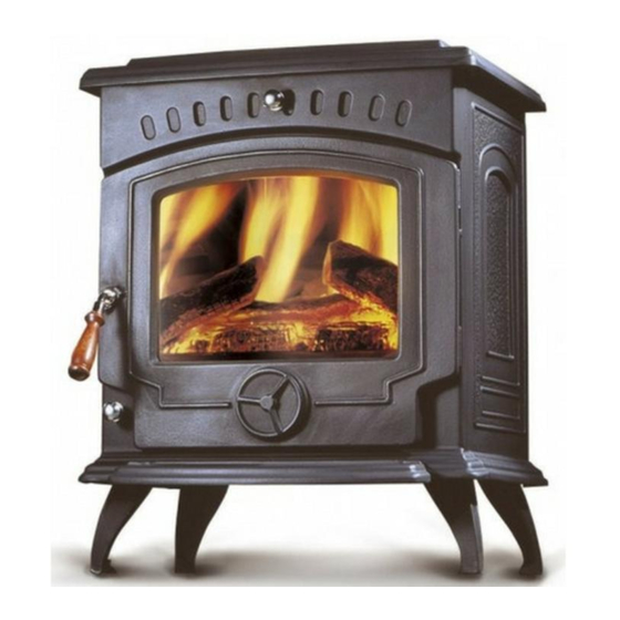
Tara
Boiler / Non Boiler & DHW
Solid Fuel Stove
WARNING: This appliance is hot while in operation and retains its heat for a long period of time after
use. children, aged or infirm persons should be supervised at all times and should not be allowed to
touch the hot working surfaces while in use or until the appliance has thoroughly cooled.
When using the boiler stove in situations where children, aged and/or infirm persons are present a fire-
guard must be used to prevent accidental contact with the stove. The fireguard should be
BS 8423:2002.
manufactured in accordance with
INSTALLATION AND OPERATING INSTRUCTIONS
Advertisement
Table of Contents

Subscribe to Our Youtube Channel
Related Manuals for Stanley Tara Boiler


Summary of Contents for Stanley Tara Boiler
- Page 1 Tara Boiler / Non Boiler & DHW Solid Fuel Stove WARNING: This appliance is hot while in operation and retains its heat for a long period of time after use. children, aged or infirm persons should be supervised at all times and should not be allowed to touch the hot working surfaces while in use or until the appliance has thoroughly cooled.
-
Page 2: Table Of Contents
TABLE OF CONTENTS PAGE NO. General ............... 4 Handling . - Page 3 TABLE OF CONTENTS PAGE NO. 34. Recommended Fuels ............15 35.
-
Page 4: General
TARA SOLID FUEL CENTRAL HEATING STOVE INSTALLATION & OPERATING INSTRUCTIONS GENERAL The complete installation must be done in accor- dance with current Standards and Local Codes. It When installing, operating and maintaining your should be noted that the requirements and these Tara Stove respect basic standards of fire safety. -
Page 5: Flues
In adverse weather conditions, down drafts may be Fig 3 2300 experienced causing smoke or fumes to spill into the room. If this occurs shut the appliance down by closing the air controls. If the problem persists seek the advice of a chimney sweep. Fig 2 Soot Door Appliance... -
Page 6: Top Flue Exit
TOP FLUE EXIT Fig. 5 For top outlet configuration remove the hob from the top of the stove, turn the hob upside down and place it on the floor, taking care not to damage it. Remove the hob blanking plate by unscrewing the two screws from underneath the hob. -
Page 7: Permanent Air Vent
It is recommended that this appliance is sited next to Joints between air vents and outside walls should be sealed to prevent the ingress of moisture. Existing and on a non-combustible surface. A minimum all air vents should be of the correct size and unob- round clearance of 100 mm will allow air circulation structed for the appliance in use. -
Page 8: Specification
SPECIFICATION BOILER STOVE Fig 7 DHW STOVE Fig 7A... -
Page 9: Non Boiler Model
NON BOILER STOVE Fig 7B Note: Dimensions stated are in millimetres and may be subject to a slight +/- variation. TECHNICAL DATA MODEL BOILER NON BOILER Fuel Coal Wood Coal Wood Coal Wood Parameter Max Heat Output (kW) Nominal Heat Output (kW) Output to Room (kW) -
Page 10: Plumbing (Boiler Model)
PLUMBING WARNING: DO NOT OBSTRUCT PRIMARY There must be no gate valves on this circuit and it AIR SUPPLY TO THE SPIN VALVE AT THE must have an expansion pipe exhausting to atmos- FRONT OF THE STOVE phere. Cylinder and pipe work should be lagged to minimise heat loss. -
Page 11: Dhw Plumbing
DHW PLUMBING SYSTEM in the unlikely event that the appliance is not operat- ing in freezing conditions the water must be drained Fig.10 from the boiler to prevent frost damage. DOMESTIC HOT WATER SYSTEM (DHW MODEL ONLY) The DHW Model must be connected to a gravity system. -
Page 12: Pipe Thermostat
PIPE THERMOSTAT Fig.12 The fitting of a pipe thermostat to the flow pipe is essential in order to activate the water circulation pump when the water reaches the selected temperature. When the water temperature falls below the select- ed temperature the pipe thermostat will cut off the water circulation pump in order to allow the boiler to recover. -
Page 13: Lighting
LIGHTING Before lighting the stove check with the installer that the installation work and commissioning checks described in the installation instructions have been carried out correctly and that the chimney has been swept clean, is sound and free from any obstructions. As part of the stove’s handover the installer should have demonstrated how to operate correctly. -
Page 14: Important Notes
IMPORTANT NOTES Now that your Stanley Solid Fuel Stove is installed and no doubt you are looking forward to many comforts it will provide, we would like to give you some tips on how to get the best results from your stove. -
Page 15: Primary Air Settings - Standard
Fig.13 This appliance has been tested using seasoned wood logs and manufactured briquetted smokeless fuel (Ancit) for closed appliances, sized between 20g and 140g. Other fuels are commercially avail- able and may give similar results. Wood logs up to 406mm long are suitable. All fuels should be stored under cover and kept as dry as possible prior to use. -
Page 16: Operation
bustion chamber. Add fuel to the fire, close fire door WARNING: and re-set spin valve to required setting. Properly installed, operated and maintained this DE-ASHING stove will not emit fumes into the dwelling. Occasional fumes from de-ashing and re-fuelling Never allow ashpan to over fill as it will cause dam- may occur. -
Page 17: To Clean Chimney Outlet (Boiler / Non Boiler Model )
TO CLEAN CHIMNEY OUTLET Replace any damaged parts and replace firebox (Boiler Model) insert and grate ensuing that the pull rod is inserted back through the opening on the left hand side of the boiler and also through the hole on the front panel. Remove baffle underneath the boiler cross flow chamber by lifting it upwards and pulling it outwards and insert cleaning brush. -
Page 18: Glass Cleaning
It is best to clean the glass when it is thoroughly cooled. Fig.20 CO ALARM Waterford Stanley recommend the fitting of a CO Alarm in the same room as the appliance, this is a GLASS REPLACEMENT requirement under UK Building Regulations. -
Page 19: Exploded View - Hpb Stove
- W00801AXX 30. TOP BAFFLE - Z00017AXX 12. PULL ROD BOX - F01077AXX 31. FIRE FENCE - Z00020AXX 13. TARA BOILER ASSY - L00125AXX 32. GRATE - Z00036AXX 14. SECONDARY AIR WASH SHUTTER - Q00247AXX 33. GRATE SUPPORT - Z00046AXX 15. -
Page 20: Exploded View - Nb Stove
TARA NB EXPLODED VIEW 23. SECONDARY AIR WASH SHUTTER - Q00247AXX OPERATING TOOL - B00009BZZ 24. DRY SHELL PROTECTION PLATE - Q00250AXX SPIN VALVE - B00012AZZ 25. AIR WASH PLATE - Q00564AXX FLUE BLANKING PLATE - B00064AZZ 26. GLASS WINDOW - T00009AXX LEG (LONG) - B00077BZZ... -
Page 21: Exploded View - Dhw Stove
TARA DHW EXPLODED VIEW 23. 2” HINGE - U00010AXX OPERATING TOOL - B00009BZZ 24. KNOB SECONDARY AIR DAMPER - U00018AXX SPIN VALVE - B00012AZZ 25. AIR WASH KNOB - U00077AXX - B00077AZZ 26. DOOR HANDLE AXLE - V00022BXX - B00209AZZ 27. -
Page 22: Installation Check List
INSTALLATION CHECK LIST Tick Flue System 1. Minimum Flue Height of 4.5 metres (15 feet). 2. Appliance should be connected to a minimum of 1.8 metres (6 feet) of 150mm (6”) flue pipe with a horizontal run not exceeding 150mm (6”). 3. - Page 23 NOTES...
- Page 24 NOTES Manufactured by Waterford Stanley Ltd., Unit 401-403, IDA Industrial Estate, Cork Road, Waterford, Ireland. Tel: (051) 302300 Fax (051) 302315 www.waterfordstanley.com N00154AXX REV:002 DP 150309...
Need help?
Do you have a question about the Tara Boiler and is the answer not in the manual?
Questions and answers