Stanley Erin Installation And Operating Instructions Manual
Boiler solid fuel stove
Hide thumbs
Also See for Erin:
Table of Contents
Advertisement
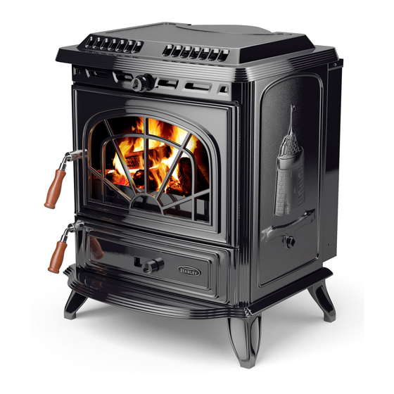
Erin
Boiler Solid Fuel Stove
INSTALLATION AND OPERATING INSTRUCTIONS
This appliance is hot while in operation and retains its heat for a long period of time after use. Children,
aged or infirm persons should be supervised at all times and should not be allowed to touch the hot
working surfaces while in use or until the appliance has thoroughly cooled.
When using the boiler stove in situations where children, aged and/or infirm persons are present a fire-
guard must be used to prevent accidental contact with the stove. The fireguard should be
manufactured in accordance with BS 6539.
Advertisement
Table of Contents

Related Manuals for Stanley Erin


Summary of Contents for Stanley Erin
- Page 1 Erin Boiler Solid Fuel Stove INSTALLATION AND OPERATING INSTRUCTIONS This appliance is hot while in operation and retains its heat for a long period of time after use. Children, aged or infirm persons should be supervised at all times and should not be allowed to touch the hot working surfaces while in use or until the appliance has thoroughly cooled.
-
Page 2: Table Of Contents
TABLE OF CONTENTS PAGE NO. General ............... 4 Handling . - Page 3 TABLE OF CONTENTS PAGE NO. 36. Fire Safety ..............16 37.
-
Page 4: General
Standards and Local Codes. It When installing, operating and maintaining your should be noted that the requirements and these Erin Stove respect basic standards of fire safety. publications may be superseded during the life of Read these instructions carefully before commenc- this manual. -
Page 5: Baffle Fitting Instructions
Fig.6 Fig.3 (G) Lift the rear of the stove and manover the pallet into the position in Fig.4, where the rear leg (K) Attach the short timber handle to the ashpit door positions are accessible and the stove rests on using the M8 x 70mm long round head screw the pallet in the centre at the back and on the and the spring washer. -
Page 6: Flues
FLUES Fig.9 Flues should be vertical wherever possible and where a bend is necessary, it should not make an angle of more than 45 with the vertical. Horizontal flue runs should be avoided except in the case of a back outlet from the appliance, when the length of the horizontal section should not exceed 150mm (6”). -
Page 7: Top Flue Exit
Flue pipes may be of any of the following materials: REAR FLUE EXIT Cast iron as described in BS 41: Fit the top cover plate to the stove with the two 1973 (1981), or screws holding on the rear exit cover plate making Stainless steel with a wall thickness sure that the sealing rope is properly seated on the of at least 1mm and as described in... -
Page 8: Location
There are several conditions to be considered in tion air requirement for this appliance use the fol- selecting a location for your Waterford Erin Stove. lowing equation: a total free area of at least 550mm per kW of rated output above 5kW shall be provid- a. -
Page 9: Flue & Water Pipe Locations
SHROUD ASSEMBLY Fig.15 STEP 1 - FIT TOP & D CONNECTOR FLUE & WATER PIPE LOCATIONS Flue outlet to suit 152mm (6”) internal diameter flue pipe. STEP 2 - FIT SIDES Water outlets 25mm (1”) B.S.P. Fig.16 STEP 3 - FIT CONTROL ROD WARNING: DO NOT OBSTRUCT PRIMARY AIR SUPPLY TO THE AIR DUCT. -
Page 10: Plumbing
Fig.17 STEP 4 - FIT CONTROL KNOB & INSERT SPLIT PIN Injector Tee Pump PLUMBING INJECTOR TEE REGULATIONS Where the gravity and central heating circuits join The plumbing must be in accordance with all together to return to the stove we recommend the relevant regulations and practices. -
Page 11: Pipe Thermostat
PIPE THERMOSTAT HANDOVER The fitting of a pipe thermostat to the flow pipe is On completion of the installation allow a suitable essential in order to activate the water circulation period of time for any fire cement and mortar to dry pump when the water reaches the selected out, when a small fire may be lit and checked to temperature. -
Page 12: Important Notes
13. Avoid contact with the appliance when in use as stove reaches very high operating temperatures. 14. This appliance should be regularly maintained by a competent service engineer. Use only replacement parts recommended by Stanley. Making unauthorised modifications, or using unautho- rised parts will invalidate your guarantee and may cause damage or injury. -
Page 13: Lighting
LIGHTING Before lighting the stove check with the installer that the installation work and commissioning checks described in the installation instructions have been carried out correctly and that the chimney has been swept clean, is sound and free from any obstructions. -
Page 14: Operating Instructions
OPERATING INSTRUCTIONS WARNING: RECOMMENDED FUELS Properly installed, operated and maintained this stove will not emit fumes into the dwelling. All fuels should be stored under cover and kept Occasional fumes from de-ashing and re-fuelling as dry as possible prior to use. may occur. -
Page 15: De-Ashing
Fig.24 Fig.23 Operating Tool The secondary air control knob is hot when the appliance is in use. The ashpan handle is a com- bined operating tool and can be used to operate this knob or use the glove provided. NOTE:- A boiler model stove will provide heat into the boil- er and also to the room in which it is situated. -
Page 16: To Clean Chimney Back Outlet
Fig.26 TO REPLACE ROCKER OPERATING SLEEVE Cleaning Firebox Chamber 1. Remove the 3 fire bars. 2. Lift the grate at the left hand end and remove it. 3. Withdraw the Rocker Operating Sleeve from under the boiler at the right hand side. Screws 4. -
Page 17: In Case Of Fire
6. A plan to deal with a chimney fire as follows:- DOOR LATCH ADJUSTMENT (a) Notify the fire department. If the door latch should be come loose over time due to compression/ hardening of the rope inside the fire (b) Prepare occupants for immediate evacua- door, an adjustment can be carried out by removing tion. -
Page 18: Glass Cleaning
(g) Replace glass only with ceramic glass 5mm thick. (See Fig.31) CO ALARM Waterford Stanley recommend the fitting of a CO Alarm in the same room as the appliance, this is a requirement under UK Building Regulations. Further guidance on the installation of a carbon monoxide alarm is available in BS EN 50292:2002 and from the alarm manufacturers instructions. -
Page 19: Exploded View
EXPLODED VIEW TOP FLUE OUTLET - B00053AZZ 27. FIRE DOOR ASSEMBLY - L00009AEN LEG (SHORT) - B00054AZZ 28. ASHPIT DOOR ASSEMBLY - L00011AEN TOP FLUE BLANKING PLATE - B00055AZZ 29. GRATE ASSEMBLY - L00019AXX ASHTRAY - B00056AZZ 30. PROTECTIVE COVER - L00616AXX - B00057BZZ 31. -
Page 20: Installation Check List
12. The room in which the appliance is located should have an air vent of adequate size to support correct combustion (see Ventilation & Combustion Air Requirement Section for specific details). Manufactured by Waterford Stanley Ltd., Unit 401-403, IDA Industrial Estate, Cork Road, Waterford, Ireland. Tel: (051) 302300 Fax (051) 302315...
Need help?
Do you have a question about the Erin and is the answer not in the manual?
Questions and answers