Advertisement
Quick Links
Advertisement

Related Manuals for BROSA Edgar Dresser


Summary of Contents for BROSA Edgar Dresser
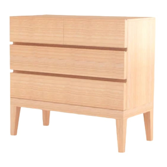
- Page 1 ASSEMBLY GUIDE Edgar Dresser...
- Page 2 Components Upon unpacking your dresser from it’s delivery box, you should have the separate pieces shown below. Follow the steps on the next pages to assemble your new dresser. Outer body of dresser Base x 1 Side panel x 2 Top panel x 1 Middle panel x 1 Leg x 4...
- Page 3 Hardware You will need...
- Page 4 Step 1 Insert a dowel in both of the inner holes of the support beam and a cam screw in the two outer holes. Align the front support beam perpendicular to the support beam and rmly press together. Insert a cam lock in both of the holes on the support beam as shown in the diagram.
- Page 5 Step 2 Insert a dowel into both inner holes of the support beam a cam screw into both holes on the outside. Dab some glue onto the end of the support beam. Align the support beam and side panel together as shown in the diagram and press together.
- Page 6 Step 3 Insert dowels into each of the four inner holes on the base and cam screws into the outer holes. Align the structure formed in Step 2 to the base and rmly press together. On the inside of the structure insert a cam lock into each of the four holes as B x 4...
- Page 7 Step 4 Align one part of the back panel to the the structure making sure the holes are facing upward and gently slide along the grooves down to the base. Insert a dowel in each of the three holes on the top of the rst back panel.
- Page 8 Step 5 Insert a dowel into the inner hole along the bottom of the middle panel and a cam screw into the outer hole. Align the middle panel inside the top tier of the structure and rmly press the middle panel to the top support beam.
- Page 9 Step 7 Insert a dowel into each of the inner holes along the top panel and a cam screw into each of the outer holes. Align the top panel to the structure and rmly press together. Insert a cam lock into each of the four holes inside the structure as shown.
- Page 10 Step 9 Align a track to a side panel for a draw and x into place with screws (H). Repeat the same process for the remaining side panels for the draws. Insert a dowel into the middle hole on the end of each panel. A x 4 H x 24 Q x 4...
- Page 11 Step 11 Align the base of the draw to the structure and slide along the grooves until it reaches the end. Repeat for the remaining draws. For the two larger draws, one by one, insert a dowel into the two outer holes on the support beam and a A x 4 cam screw in the middle hole.
- Page 12 Step 12 For the smaller draw, insert cam screws into the outer four holes on the panel. Align the front panel to the structure and rmly press together. Insert cam locks into the holes on the outside of the structure followed by a plastic cap (R).
- Page 13 Step 13 For the larger draw, insert a dowel into the two outer holes of the support beam and a cam screw into the middle hole. en follow the same process from the last step to attach the front panel to the structure not forgetting to insert a cam lock into the support beam at the end of the process and repeat for the second draw.
- Page 14 Step 15 Place a stopper along the side of the back of the dresser as shown in the diagram and follow it with a screw to secure it in place. L x 6 M x 6 Step 16 Enjoy your new dresser!
Need help?
Do you have a question about the Edgar Dresser and is the answer not in the manual?
Questions and answers