Table of Contents
Advertisement
Quick Links
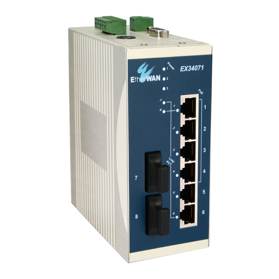
This quick start guide describes how to install and use the Hardened PoE Ethernet Switch.
-10°C to +60°C, this is the switch of choice for harsh environments constrained by space.
Physical Description
The Terminal Block and Power inputs
DC Terminal Block Power Inputs: There are two pairs of power inputs can be used to power up this switch. Redundant power supplies function is
supported.
The 10/100Base-TX and 100Base-FX Connectors
The 10/100Base-TX Connections
The following lists the pinouts of 10/100Base-TX ports.
The 100Base-FX Connections
The fiber port pinouts
The Tx (transmit) port of device I is connected to the Rx (receive) port of device II, and the Rx (receive) port of
device I to the Tx (transmit) port of device II.
The WDM 100Base-FX Connections
The fiber port pinouts
Only one single-mode optical fiber is required to transmit and receive data.
Hardened PoE Ethernet Switch
Pin
1
2
3
4
5
6
7
8
1
Capable of operating at temperature extremes of
Power Input Assignment
Power3
48VDC
+
48VDC
Power2
-
Power Ground
+
48VDC
Power1
-
Power Ground
Earth Ground
Relay Alarm Assignment
*Relay warning signal disable for following:
1. The relay contact closes if Power1 and
Power2 are both failed but Power3 on.
FAULT
2. The relay contact closes if Power3 is failed
but Power1 and Power2 are both on.
Regular Ports
Output Transmit Data +
Output Transmit Data -
Input Receive Data +
NC
NC
Input Receive Data -
NC
NC
DC Jack
Terminal Block
Uplink port
Input Receive Data +
Input Receive Data -
Output Transmit Data +
NC
NC
Output Transmit Data -
NC
NC
Advertisement
Table of Contents

Related Manuals for EtherWAN EX34000 Series


Summary of Contents for EtherWAN EX34000 Series
- Page 1 Hardened PoE Ethernet Switch This quick start guide describes how to install and use the Hardened PoE Ethernet Switch. Capable of operating at temperature extremes of -10°C to +60°C, this is the switch of choice for harsh environments constrained by space. Physical Description The Terminal Block and Power inputs Power Input Assignment...
- Page 2 Hardened PoE Ethernet Switch The Port Status LEDs State Indication 10/100Base-TX, 100Base-FX Steady A valid network connection established. Link/ACT Transmitting or receiving data. (Green) Flashing ACT stands for ACTIVITY. Functional Description • Meets IEC61000-6-2 EMC Generic Standard Immunity for industrial environment. •...
Need help?
Do you have a question about the EX34000 Series and is the answer not in the manual?
Questions and answers