Sign In
Upload
Download
Table of Contents
Contents
Add to my manuals
Delete from my manuals
Share
URL of this page:
HTML Link:
Bookmark this page
Add
Manual will be automatically added to "My Manuals"
Print this page
×
Bookmark added
×
Added to my manuals
Manuals
Brands
EtherWAN Manuals
Switch
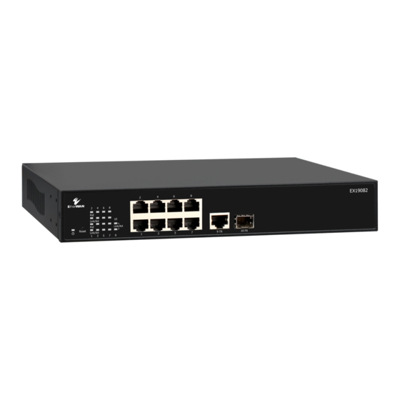
EX19082
User manual
EtherWAN EX19082 User Manual
Smart managed switches
Hide thumbs
Also See for EX19082
:
Installation manual
(2 pages)
1
2
3
4
Table Of Contents
5
6
7
8
9
10
11
12
13
14
15
16
17
18
19
20
21
22
23
24
25
26
27
28
29
30
31
32
33
34
35
36
37
38
39
40
41
42
43
44
45
46
47
48
49
50
51
52
53
54
55
56
57
58
59
60
61
62
63
64
65
66
67
68
69
70
71
72
73
page
of
73
Go
/
73
Contents
Table of Contents
Troubleshooting
Bookmarks
Table of Contents
Changes in this Revision
Document Conventions
References to Switch Models
Table of Contents
1 Introduction
Key Features
Model EX19082 Features
Model EX19164 Features
Model EX19244 Features
Common Features
Quick Start Guide
2 Unpacking and Installation
Unpacking the Hardware
System Requirements
Hardware Features
Front Panel
Rear Panel
Side and Bottom Panels
Installing the Switch
Preparing the Site
Installing the Switch
Connecting to the 10/100/1000 Mbps RJ-45 Ports
Connecting to the SFP Ports
Checking the Installation
Applying AC Power
Where to Go from here
3 Preparing to Configure the Switch
Connecting the PC
Configuring TCP/IP Settings for Windows 10
Disabling Firewall and Security Software
4 Configuring the Switch
Logging in to the Web Management Interface
Idle Time Security
Understanding the Web Management Interface
Web Management Interface Menus
Configuration Menu
Monitoring Menu
Maintenance Menu
5 Troubleshooting
Troubleshooting Chart
Additional Troubleshooting Suggestions
Network Adapter Cards
Configuration
Switch Integrity
Auto-Negotiation
Appendix A - Specifications
Technology
Power
Mechanical
Interface
Environment
Regulatory Approvals
Advertisement
Quick Links
Download this manual
EX19082, EX19164, and EX19244
Smart Managed Switches
FastFind Links
Introduction
User's Guide
Unpacking and Installation
Preparing to Configure the Switch
Configuring the Switch
Table of
Contents
Previous
Page
Next
Page
1
2
3
4
5
Advertisement
Table of Contents
Troubleshooting
Troubleshooting
67
Troubleshooting Chart
68
Additional Troubleshooting Suggestions
69
Need help?
Do you have a question about the EX19082 and is the answer not in the manual?
Ask a question
Questions and answers
Related Manuals for EtherWAN EX19082
Switch EtherWAN EX19082 Installation Manual
Smart-managed switch (2 pages)
Switch EtherWAN EX19164 Installation Manual
Smart-managed switch (2 pages)
Switch EtherWAN EX19244 User Manual
Smart managed switches (73 pages)
Switch EtherWAN EX19164A Installation Manual
(2 pages)
Switch EtherWAN EX19162A Installation Manual
Poe switch (2 pages)
Switch EtherWAN EX19162 Installation Manual
Smart-managed switch (2 pages)
Switch EtherWan EX17082 User Manual
Web-smart switches (99 pages)
Switch EtherWAN EX1624W User Manual
24-port web-smart ethernet switch (25 pages)
Switch EtherWAN EX17016 User Manual
(97 pages)
Switch EtherWAN EX16908 Quick Start Manual
(17 pages)
Switch EtherWAN EX17908 Series User Manual
Web-smart switch (72 pages)
Switch EtherWAN EX72129A User Manual
Etherwan managed switch (297 pages)
Switch EtherWAN EX42905 Series Quick Start Manual
(20 pages)
Switch EtherWAN EX45900 series Quick Start Manual
Hardened poe gigabit ethernet switch (19 pages)
Switch EtherWAN EX17016 Installation Manual
Web-smart switch (2 pages)
Switch EtherWAN EX17162 Installation Manual
Web-smart switch (2 pages)
This manual is also suitable for:
Ex19164
Ex19244
Table of Contents
Print
Rename the bookmark
Delete bookmark?
Delete from my manuals?
Login
Sign In
OR
Sign in with Facebook
Sign in with Google
Upload manual
Upload from disk
Upload from URL


Need help?
Do you have a question about the EX19082 and is the answer not in the manual?
Questions and answers