
Related Manuals for EtherWAN EX17016


Summary of Contents for EtherWAN EX17016
- Page 1 EX17008 and EX17016 Web-Smart Switches FastFind Links Introduction User’s Guide Unpacking and Installation Preparing to Configure the Switch Configuring the Switch...
- Page 2 Disclaimer of Liability The information contained in this document is subject to change without notice. EtherWAN is not liable for any errors or omissions contained herein or for resulting damage in connection with the information provided in this manual.
-
Page 3: Preface
This section provides a history of the revision changes to this document. Revision Document Version Date Description Version 1 08/052014 Initial release Changes in this Revision N/A - this is first version of this document. EX17008 and EX17016 Web-Smart Switches User Guide... -
Page 4: Document Conventions
[ ] square Indicates optional values. brackets { } braces Indicates required or expected values. | vertical bar Indicates that you have a choice between two or more options or arguments. EX17008 and EX17016 Web-Smart Switches User Guide... -
Page 5: References To Switch Models
References to Switch Models This guide covers the EX17008 and EX17016 Web-Smart Switches from EtherWAN Systems, Inc. When information in this guide applies to both models, the models are referred to collectively as “the switch.” If information applies to specific models only, those models are identified by model name (either EX17008 or EX17016). -
Page 6: Table Of Contents
Preparing the Site ....................18 Installing the Switch ................... 18 Connecting to the 10/100 Mbps RJ-45 Ports ............. 20 Checking the Installation ..................20 Applying AC Power .................... 20 Where to Go from Here ................... 21 EX17008 and EX17016 Web-Smart Switches User Guide... - Page 7 Logout Menu ..................... 86 5 Troubleshooting....................87 Troubleshooting Chart ..................... 88 Additional Troubleshooting Suggestions ..............89 Network Adapter Cards ..................89 Configuration ..................... 89 Switch Integrity ....................89 Auto-Negotiation ....................89 Technology ......................90 EX17008 and EX17016 Web-Smart Switches User Guide...
- Page 8 Power ........................90 Mechanical ......................91 Interface ........................91 Environment ......................91 Regulatory Approvals ....................92 Index ........................94 viii EX17008 and EX17016 Web-Smart Switches User Guide...
-
Page 9: Introduction
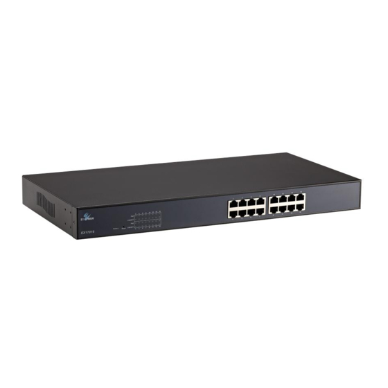
1 Introduction Topics: Congratulations on your purchase of the EX17008 or EX17016 Web-Smart Switch from EtherWAN Systems, Inc. Your switch is a Key Features (page 11) state-of-the-art IEEE-compliant network solution designed for Quick Start Guide (page users who require high-performance along with the power of management to eliminate bottlenecks and increase productivity. - Page 10 Figure 1-1. EX17008 Series Switch Figure 1-2. EX17016 Series Switch EX17008 and EX17016 Web-Smart Switches User Guide...
-
Page 11: Key Features
Key Features This section summarizes the key features of the EX17008 and EX17016 switches. Model EX17008 Features 8 10/100BASE-TX ports supporting IEEE 802.3af Power over Ethernet (PoE) Power Sourcing Equipment (PSE), with a total PoE power budget of 123.2 W Max. -
Page 12: Quick Start Guide
Connect the other end to a 10/100 Mbps RJ-45 port on the switch: Model EX17008: use ports 1 through 8. Model EX17016: use ports 1 through 16. Repeat this step for each additional device you want to connect to the 10/100 Mbps ports. -
Page 13: Unpacking And Installation
This chapter describes how to unpack and install the EX17008 and EX17016 switches. Unpacking the Hardware (page 14) System Requirements (page 14) Hardware Features (page Installing the Switch (page Where to Go from Here (page 21) EX17008 and EX17016 Web-Smart Switches User Guide... -
Page 14: Unpacking The Hardware
One CD containing this user’s guide If any item is damaged or missing, notify your authorized EtherWAN representative. Keep the carton, including the original packing material, in case you need to store the product or return it. System Requirements... -
Page 15: Hardware Features
Hardware Features The following sections describe the hardware features of the EX17008 and EX17016 switches. Front Panel Figure 2-1 and Figure 2-2 show the front panels of the EX17008 and EX17016 switches. Reset 10/100 Button Mbps Ports Status LEDs Figure 2-1. Front Panel of the EX17008 Switch... - Page 16 Reset Button The EX17008 and EX17016 front panels have a reset button to reset the switch to its factory default settings. This button is recessed to prevent accidental resets of the switch.
-
Page 17: Rear Panel
Figure 2-4. Rear Panel of the EX17016 Switch Side and Bottom Panels The EX17008 and EX17016 side panels have vents for cooling. Be sure these vents are not blocked. The bottom panel has a product label that shows regulatory compliance, product serial number, and other information. -
Page 18: Preparing The Site
If installing the switch in a rack, attach the supplied rack-mounting brackets to the switch's front panel (one on each side), and secure them with the screws provided with the equipment rack. For more information, refer to the documentation that came with the equipment rack. EX17008 and EX17016 Web-Smart Switches User Guide... - Page 19 Figure 2-5. EX17008 Switch Dimensions Figure 2-6. EX17016 Switch Dimensions EX17008 and EX17016 Web-Smart Switches User Guide...
-
Page 20: Connecting To The 10/100 Mbps Rj-45 Ports
Applying AC Power EX17008 and EX17016 switches have an ON/OFF switch that controls power to the switch. Before you connect the power cord, select an AC outlet that is not controlled by a wall switch, which can turn off power to the switch. After you select an appropriate outlet, use the following procedure to apply AC power. -
Page 21: Where To Go From Here
If this does not resolve the problem, see Chapter 5, Troubleshooting. Where to Go from Here After you power-up the switch for the first time, you configure it using the switch’s built-in management software. For more information, see Chapters 3 and 4. EX17008 and EX17016 Web-Smart Switches User Guide... -
Page 22: Preparing To Configure The Switch
7 operating system. If your PC is running an operating system other than Windows 7, refer to the documentation for your operating system to find out how to change the PC’s TCP/IP settings. EX17008 and EX17016 Web-Smart Switches User Guide... -
Page 23: Connecting The Pc
1. Click Start >Control Panel > Network and Internet >View network status and tasks. 2. In the left pane, click Change adapter settings. 3. On the right side of the page, select the connection, right click it, and then select Properties. EX17008 and EX17016 Web-Smart Switches User Guide... - Page 24 0 and 255, except the number 1 because the address 192.168.2.1 is already being used by the switch. 7. Press the Tab key to populate the Subnet mask field automatically. You can leave the Default gateway field blank. EX17008 and EX17016 Web-Smart Switches User Guide...
-
Page 25: Disabling Proxy Settings
Click OK until the Internet Options window appears. In the Internet Options window, under Temporary Internet Files, click Settings. For the option Check for newer versions of stored pages, select Every time I visit the webpage. EX17008 and EX17016 Web-Smart Switches User Guide... -
Page 26: Disabling Proxy Settings In Firefox
Select your connection method. If using a wired connection, select Built-in Ethernet. For wireless, select Airport. Click the Proxies tab. Be sure each proxy in the list is unchecked. Click Apply Now to finish. EX17008 and EX17016 Web-Smart Switches User Guide... -
Page 27: Disabling Firewall And Security Software
If you encounter problems connecting to the switch, disable any firewall or security software that may be running on your PC before configuring the switch. For more information, refer to the documentation for your firewall. EX17008 and EX17016 Web-Smart Switches User Guide... -
Page 28: Configuring The Switch
Logging in to the Web chapter to configure the switch. Management Interface (page 29) Idle Time Security (page Understanding the Web Management Interface (page 30) Web Management Interface Menus (page EX17008 and EX17016 Web-Smart Switches User Guide... -
Page 29: Logging In To The Web Management Interface
5. Click OK. The Web management interface starts and the page in Figure 4-2 appears. Note: First-time logins must change the switch’s system IP configuration settings (see page 36) and default username and password (see page 35). EX17008 and EX17016 Web-Smart Switches User Guide... -
Page 30: Idle Time Security
Understanding the Web Management Interface The top of the Web management interface shows the switch ports, with ports in use highlighted in green. In Figure 4-2, for example, the ports for the EX17016 switch are shown, with port 16 in use. - Page 31 Figure 4-3. Example of Administrator Submenus Note: Depending on the switch model you have, the number of ports shown in the screens in this chapter might differ from the number of ports shown in your Web management screens. EX17008 and EX17016 Web-Smart Switches User Guide...
-
Page 32: Web Management Interface Menus
QoS Setting > Class of Service Configuration Uses Class of Service (CoS) to set up consistent traffic prioritization policies. QoS Setting > TCP/UDP Port Number QoS Configure CoS settings based on the protocol associated with packets. EX17008 and EX17016 Web-Smart Switches User Guide... - Page 33 Configuration Backup/Recovery Saves and restores the switch configuration. Miscellaneous Configures output queuing aging time, VLAN striding, and IGMP snooping versions 1 and 2. Logout Logs you out of the current Web management interface session. EX17008 and EX17016 Web-Smart Switches User Guide...
-
Page 34: Administrator Menu
Local default settings returns the switch to its default configuration. See page 38. Firmware Update updates the switch firmware. See page 39. Reboot Device reboots the switch. See page 40. EX17008 and EX17016 Web-Smart Switches User Guide... - Page 35 For security purposes, every typed character is masked as a dot (). 4. Click Update. 5. When a message tells you that the update was successful and prompts you to reboot the switch, click Reboot. EX17008 and EX17016 Web-Smart Switches User Guide...
- Page 36 The IP address must be unique and must not be used by any other device on the network. Note: The IP Address, Subnet Mask, and Gateway fields are not available when IP Configure is set to DHCP. 3. Click Update. EX17008 and EX17016 Web-Smart Switches User Guide...
-
Page 37: System Status Page
A-Z, digits 0-9, underscore (_), plus sign (+), minus sign (-), and equals sign (=). System Version Read-only field that shows the system software version. Update Button After configuring the settings on this page, click this button to commit your settings. EX17008 and EX17016 Web-Smart Switches User Guide... - Page 38 The username and password configured in the Administrator > Authentication Configuration page. To reset the switch’s IP address, comment, and username and password, reset the switch using the reset button (see “Reset Button” on page 16). EX17008 and EX17016 Web-Smart Switches User Guide...
- Page 39 Path: Administrator > Firmware Update The Firmware Update page lets you upgrade the switch firmware. After you obtain the upgraded firmware file from EtherWAN, use the fields in this page to upgrade the switch firmware. 1. In the Password field, enter the case-sensitive password used to access the Web management interface.
- Page 40 Path: Administrator > Reboot Device The Reboot Device page has a Confirm button that reboots the switch. This button is functionally equivalent to pressing the reset button on the switch (see “Reset Button” on page 16). EX17008 and EX17016 Web-Smart Switches User Guide...
-
Page 41: Port Management Menu
Broadcast Storm Control prevents LAN traffic from being disrupted by a broadcast, multicast, or unicast storm on a port. See page 50. POE enables or disables PoE on switch ports. See page 51. EX17008 and EX17016 Web-Smart Switches User Guide... - Page 42 The bottom section is a read-only area that shows the current status and settings of the switch ports. See “Port Configuration Fields” on page 44. Configure Switch Ports Here Current Status and Settings EX17008 and EX17016 Web-Smart Switches User Guide...
-
Page 43: Configuring Switch Ports
Allows the switch to learn the MAC addresses of the stations in the network to identify on which port to send traffic. Choices are: Enable = enable address learning. Disable = disable address learning. EX17008 and EX17016 Web-Smart Switches User Guide... -
Page 44: Port Configuration Fields
Shows whether backpressure is enabled (ON) or disabled (OFF) for the ports. Tx Cap Shows whether the port is configured to send data. Addr. Learning Shows whether address learning is enabled (ON) or disabled (OFF) for the ports. EX17008 and EX17016 Web-Smart Switches User Guide... - Page 45 2. Using the Monitored Packets drop-down list, click the packets that are to be mirrored. Choices are: – Disable = disables mirroring. – Rx = receive packets. – Tx = transmit packets. – Tx & Rx = transmit and receive packets. EX17008 and EX17016 Web-Smart Switches User Guide...
- Page 46 3. Next to Source Port, check the ports you want to designate as source ports. 4. Click Update. EX17008 and EX17016 Web-Smart Switches User Guide...
- Page 47 The bottom section is a read-only area that shows the current status and setting status of the switch ports. See “Bandwidth Control Fields” on page 49. Configure Bandwidth Control Here Switch Port Status and Settings Model EX17008 Switch EX17008 and EX17016 Web-Smart Switches User Guide...
- Page 48 Configure Bandwidth Control Here Switch Port Status and Settings Model EX17016 Switch EX17008 and EX17016 Web-Smart Switches User Guide...
- Page 49 1. Using the Port No. drop-down list, click the switch port you want to configure. 2. In the Tx Rate Value field (EX17008 switch) or Tx Rate field (EX17016 switch), enter a transmission rate from 0 to 255 (0 = full speed).
- Page 50 A higher threshold allows more packets to pass through. 2. Next to Enable Port, check each port to which you want to apply broadcast storm control. 3. Click Update. EX17008 and EX17016 Web-Smart Switches User Guide...
- Page 51 Status of the minimum output power. Power POE Class Each POE port detects the class of the attached PD. Update Button After configuring the settings on this page, click this button to commit your settings. EX17008 and EX17016 Web-Smart Switches User Guide...
-
Page 52: Vlan Setting Menu
VLAN Setting > VLAN Mode page determine whether the packet is tagged automatically. Each port has a default VLAN ID setting that is user-configurable. The VLAN ID for each port can be changed on the VLAN Membership page. EX17008 and EX17016 Web-Smart Switches User Guide... - Page 53 VLAN Member allows ports to join a VLAN. See page 58. Multi to 2 Setting configures two physical switch ports to a single destination port. This page applies to port-based VLANs only. See page 61. EX17008 and EX17016 Web-Smart Switches User Guide...
- Page 54 The VLAN information within an Ethernet frame is referred to as a tag or tagged header. A tag, which follows the source and destination addresses in a frame, contains the VID of the EX17008 and EX17016 Web-Smart Switches User Guide...
- Page 55 Changing to a Port-Based VLAN If a VLAN Mode page similar to the following appears, the switch is configured for tagged-based VLAN. To switch to a port-based VLAN: 1. Click Change VLAN Mode. The following warning appears. EX17008 and EX17016 Web-Smart Switches User Guide...
- Page 56 Changing to a Tagged-Based VLAN If the VLAN Mode page appears as shown below, the switch is configured for port-based VLAN. To switch to a tagged-based VLAN: 1. Click Change VLAN Mode. The following warning appears. EX17008 and EX17016 Web-Smart Switches User Guide...
- Page 57 VLAN mode). If you clicked Continue, a page similar to the following appears. 3. Next to Tag Mode, click whether the ports should add, ignore, or remove tags in the frames they forward to other nodes on the network. 4. Click Update. EX17008 and EX17016 Web-Smart Switches User Guide...
- Page 58 1. Using the Port drop-down list, select a port number, and then click Read. 2. On the select rows, check each destination port that you want to make a member of this VLAN. Uncheck each port that you do not want to make a member. EX17008 and EX17016 Web-Smart Switches User Guide...
- Page 59 3. On the select rows, check the destination ports that you want to add as members, and uncheck the ones you do not want as members. Note: If you do not check any VLAN member ports, this VID is treated as a VID embedded in an 802.1Q tag. EX17008 and EX17016 Web-Smart Switches User Guide...
- Page 60 4. On the Port/PVID Index rows, change the default VLAN ID that is assigned to an access port to designate the virtual LAN segment to which this port is connected. 5. Click Update. A list of the VLAN members appears at the bottom of the page. EX17008 and EX17016 Web-Smart Switches User Guide...
- Page 61 1. Using the Destination Port No. drop-down lists, click the destination port numbers. 2. On the Disable Port row, check each physical port on the switch that you want to exchange packets with the destination port. 3. Click Update. Model EX17008 Switch EX17008 and EX17016 Web-Smart Switches User Guide...
- Page 62 Model EX17016 Switch EX17008 and EX17016 Web-Smart Switches User Guide...
-
Page 63: Per Port Counter Menu
Per Port Counter Menu The Per Port Counter menu lets you perform the following task: Port Counter displays the number of packets transmitted and received for each port. See page 64. EX17008 and EX17016 Web-Smart Switches User Guide... - Page 64 Receive packet and CRC error packet 2. Click Update. The page is refreshed and the information you requested is displayed. Buttons at the bottom of the page let you refresh and clear the values shown on the page. EX17008 and EX17016 Web-Smart Switches User Guide...
-
Page 65: Trunk Setting Menu
Trunk Setting Menu The Trunk Setting menu lets you perform the following task: Trunk Setting configures up to two port trunks. See page EX17008 and EX17016 Web-Smart Switches User Guide... - Page 66 The ports must be on the same VLANs. To configure trunks: 1. Next to Trunk Hash Algorithm Selection, click the trunk host algorithm you want to use. Choices are: EX17008 and EX17016 Web-Smart Switches User Guide...
- Page 67 2. Next to Trunk 0, check the physical switch ports that will make up the first trunk (trunk 0). 3. If you want a second trunk, next to Trunk 1, check the physical switch ports that will make up the second trunk (trunk 1). 4. Click Update. EX17008 and EX17016 Web-Smart Switches User Guide...
-
Page 68: Qos Setting Menu
Class of Service Configuration uses Class of Service (CoS) to set up consistent traffic prioritization policies. See page 70. TCP/UDP Port Number QoS configure CoS settings based on the protocol associated with packets. See page EX17008 and EX17016 Web-Smart Switches User Guide... - Page 69 These selections define the number of packets taken from the queue each time the weighted round robin (WRR) scheduler runs through the queues in sequence. Choices are 1 through 8 for each queue. 3. Click Update. EX17008 and EX17016 Web-Smart Switches User Guide...
- Page 70 For example, to give packets that have VLAN tags and arrive on port 2 a higher priority than packets on other ports that do not have VLAN tags, check VLAN Tag for Port No. 2. 2. Click Update. EX17008 and EX17016 Web-Smart Switches User Guide...
- Page 71 When you click QoS Setting > TCP/UDP Port Number QoS, the screen that appears depends on the switch model you have. Although the name of the page differs between models, both pages let you configure CoS settings based on protocols and other criteria. Model EX17008 Switch EX17008 and EX17016 Web-Smart Switches User Guide...
- Page 72 Drop = incoming packets are discarded at the source port. 2. The User Define Port range row lets you specify up to three user-defined ports, designated Define A, Define B, and Define C EX17008 and EX17016 Web-Smart Switches User Guide...
- Page 73 4. The Enable Port row lets you select (check) or deselect (uncheck) the ports to which the settings on this page are applied. 5. Using the TCP/UDP port number QoS function drop-down list, select whether you want to enable or disable the settings on this page. 6. Click Update. EX17008 and EX17016 Web-Smart Switches User Guide...
-
Page 74: Security Menu
TCP/UDP Filter processes or drops incoming packets based on protocols. See page 79. The Security menu for the Model EX17016 switch lets you perform the following tasks: Mac Address Filter configure the switch to drop packets ... - Page 75 5. If address learning is enabled, a message warns you that enabling MAC address binding disables address learning automatically. Click OK to remove the message and enable MAC address binding (or click Cancel to abort the operation). EX17008 and EX17016 Web-Smart Switches User Guide...
- Page 76 The fields at the bottom area of the MAC Address Binding page show the current MAC address binding status of the switch ports. Field Description Port No. Port numbers for each switch port. Filter Status MAC address filter status of the port. EX17008 and EX17016 Web-Smart Switches User Guide...
- Page 77 MAC Address Configuration Page (Model EX17016 Switch) Path: Security > MAC Address Filter The MAC Address Configuration page for the Model EX17016 switch lets you configure the switch to drop packets with specific source or destination MAC addresses. This feature is disabled by default and supports only unicast static addresses.
- Page 78 The fields at the bottom area of the MAC Address Configuration page show the current MAC address filter status of the switch ports. Field Description Port No. Port numbers for each switch port. Filter Status MAC address filter status of the port. EX17008 and EX17016 Web-Smart Switches User Guide...
- Page 79 3. For Secure Port, check the port where the packet is to be forwarded or dropped. 4. For Protocol, check the protocols you want forwarded (if Port Filtering Rule = allow) or dropped (if Port Filtering Rule = deny). 5. Click Update. EX17008 and EX17016 Web-Smart Switches User Guide...
-
Page 80: Configuration Backup/Recovery Menu
Configuration Backup/Recovery Menu The Configuration Backup/Recovery menu lets you perform the following task: Configuration Backup/Recovery saves and restores the switch configuration. See page 81. EX17008 and EX17016 Web-Smart Switches User Guide... - Page 81 (or “.bin”) file that you saved previously on your computer. To save the switch configuration: 1. Under Backup (Switch -> PC), click Download. 2. When the File Download dialog box appears, click Save. EX17008 and EX17016 Web-Smart Switches User Guide...
- Page 82 Open. 3. In the Password field, enter the same password you use to log into the Web management interface. 4. Click Update. EX17008 and EX17016 Web-Smart Switches User Guide...
-
Page 83: Miscellaneous Menu
Miscellaneous Menu Path: Miscellaneous The Miscellaneous menu lets you perform the following task: Miscellaneous configures output queuing aging time, VLAN striding, and IGMP snooping versions 1 and 2. See page 84. EX17008 and EX17016 Web-Smart Switches User Guide... - Page 84 Once enabled, the switch monitors the aging timer for each packet before it is sent out. A packet that stays in a queue for a long time will be discarded. EX17008 and EX17016 Web-Smart Switches User Guide...
- Page 85 Protocol (IGMP) report packets automatically. If you enable Leave packet will be forwarded to IGMP router ports and members want to leave this multicast group, the IGMP leave packet will be forwarded to the router ports. EX17008 and EX17016 Web-Smart Switches User Guide...
-
Page 86: Logout Menu
When you click this menu, the prompt below asks whether you want to log out. Click Accept to logout and end your session or click Back to remain in the current session. EX17008 and EX17016 Web-Smart Switches User Guide... -
Page 87: Troubleshooting
5 Troubleshooting Topics: This chapter provides information about troubleshooting the switch. Troubleshooting Chart (page 88) Additional Troubleshooting Suggestions (page 89) EX17008 and EX17016 Web-Smart Switches User Guide... -
Page 88: Troubleshooting Chart
Break the loop by ensuring that there is only one path from any networked continuously on all path) has been created. device to any other networked device. connected ports and the network is disabled. EX17008 and EX17016 Web-Smart Switches User Guide... -
Page 89: Additional Troubleshooting Suggestions
(see “Reset Button” on page 16) or use the Administrator > Reboot Device page on the switch’s Web management interface (see “Reboot Device Page” on page 40). If the problem continues, contact EtherWAN Systems technical support. Auto-Negotiation The 10/100 Mbps ports negotiate the correct duplex mode and speed if the switch is configured for auto-negotiation (this is the switch’s default setting) and the device at the other... -
Page 90: Technology
PoE power budget: 123.2 W Max. Model EX17016: Device: Max. 13.5 W (without PoE) PoE power budget: 246.4 W Max. PoE Power Output: IEEE802.3af: up to 15.4 W/port, 47 – 55 VDC, 350 mA Max. EX17008 and EX17016 Web-Smart Switches User Guide... -
Page 91: Mechanical
Per unit: Power Status Per port: Link/Activity, PoE Act/status Environment Specification Description Operating Temperature: 0°C to 45°C (32°F to 113°F) Storage Temperature: -10°C to 70°C (14°F to 158°F) Ambient Relative 10% to 95% (non-condensing) Humidity: EX17008 and EX17016 Web-Smart Switches User Guide... -
Page 92: Regulatory Approvals
Regulatory Approvals Specification Description ISO: Manufactured in an ISO9001 facility Emission Compliance: FCC Part 15, Class B, CE mark Class B Safety: UL60950-1, EN60950-1, IEC60950-1 EX17008 and EX17016 Web-Smart Switches User Guide... - Page 93 EX17008 and EX17016 Web-Smart Switches User Guide...
-
Page 94: Index
QoS Setting, 68 Default settings, loading, 38 Security, 74 DHCP, 36 Trunk Setting, 65 Disabling proxy settings, 25 VLAN Setting, 52 Duplex, 43, 44 Minimum output power, 51 Dynamic IP address, 36 Mirroring ports, 45 EX17008 and EX17016 Web-Smart Switches User Guide... - Page 95 Web management interface, 40 member, 58 Receive packets, 64 mode, 54 Recovery, 81, 83 Setting menu, 52 Reset button, 16 striding, 85 Security menu, 74 Web management interface, 30 Specifications, 90 EX17008 and EX17016 Web-Smart Switches User Guide...
- Page 96 TCP/UDP Filter Configuration, 79 Bandwidth Control, 47 TCP/UDP Port Based, 71 Broadcast Storm Control, 50 Trunk Configuration, 66 Class of Service Configuration, 70 VLAN Member, 58 Configuration Backup/Recovery, 81, 83 VLAN Mode, 54 Counter Category, 64 EX17008 and EX17016 Web-Smart Switches User Guide...
- Page 97 TEL: +886 -2- 6629-8986 Email: info@etherwan.com.tw EtherWAN has made a good faith effort to ensure the accuracy of the information in this document and disclaims the implied warranties of merchantability and fitness for a particular purpose, and makes no express warranties, except as may be stated in its written agreement with and for its customers.
Need help?
Do you have a question about the EX17016 and is the answer not in the manual?
Questions and answers