Advertisement
Quick Links
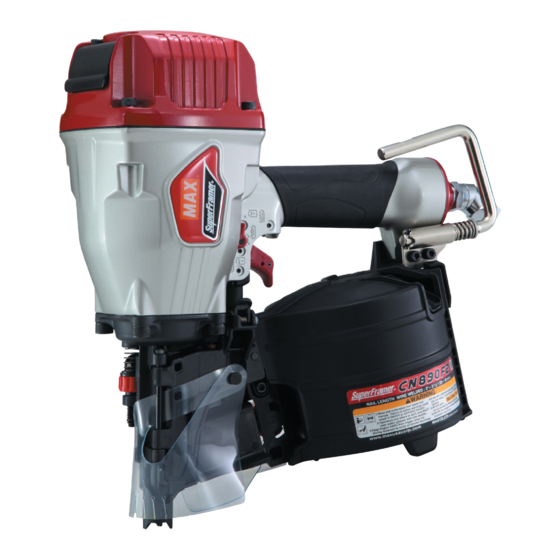
CN890F2
PNEUMATIC FRAMING COIL NAILER
DISPOSITIVO NEUMÁTICO DE CLAVETEADO
DE BOBINA DE TEJADO
CLOUEUR A BOBINE DE TOITURE PNEUMA-
TIQUE
OPERATING AND MAINTENANCE MANUAL
MANUEL D'UTILISATION ET D'ENTRETIEN
MANUAL DE OPERACIONES Y MANTENIMIENTO
BEFORE USING THIS TOOL, STUDY THIS MANUAL TO ENSURE SAFETY WARNING AND IN-
STRUCTIONS.
KEEP THESE INSTRUCTIONS WITH THE TOOL FOR FUTURE REFERENCE.
WARNING
AVANT D'UTILISER CET OUTIL, LIRE CE MANUEL ET LES CONSIGNES DE SÉCURITÉ AFIN DE
GARANTIR UN FONCTIONNEMENT SÛR.
CONSERVER CE MANUEL EN LIEU SÛR AVEC L'OUTIL AFIN DE POUVOIR LE CONSULTER UL-
TÉRIEUREMENT.
AVERTISSEMENT
ANTES DE UTILIZAR ESTA HERRAMIENTA, LEA DETENIDAMENTE ESTE MANUAL PARA FAMILIARIZARSE CON
LAS ADVERTENCIAS E INSTRUCCIONES DE SEGURIDAD.
CONSERVE ESTAS INSTRUCCIONES JUNTO CON LA HERRAMIENTA PARA FUTURAS CONSULTAS.
ADVERTENCIA
Advertisement

Related Manuals for Max SuperFramer CN890F2


Summary of Contents for Max SuperFramer CN890F2
- Page 1 CN890F2 PNEUMATIC FRAMING COIL NAILER DISPOSITIVO NEUMÁTICO DE CLAVETEADO DE BOBINA DE TEJADO CLOUEUR A BOBINE DE TOITURE PNEUMA- TIQUE OPERATING AND MAINTENANCE MANUAL MANUEL D'UTILISATION ET D'ENTRETIEN MANUAL DE OPERACIONES Y MANTENIMIENTO BEFORE USING THIS TOOL, STUDY THIS MANUAL TO ENSURE SAFETY WARNING AND IN- STRUCTIONS.
- Page 2 INDEX INDEX ÍNDICE ENGLISH Page to 11 FRANÇAIS Page to 21 ESPAÑOL Page to 31 DEFINITIONS OF SIGNAL WORDS WARNING: Indicates a potentially hazardous situation which, if not avoided, could result in death or serious injury. CAUTION: Indicates a potentially hazardous situation which, if not avoided, may result in mi- nor or moderate injury.
-
Page 3: Table Of Contents
ENGLISH OPERATING AND MAINTENANCE MANUAL INDEX 1. GENERAL SAFETY WARNINGS ............3 2. SAFETY WARNING ................4 3. SPECIFICATIONS AND TECHNICAL DATA ........7 4. AIR SUPPLY AND CONNECTIONS............7 5. INSTRUCTIONS FOR OPERATION............8 6. MAINTAIN FOR PERFORMANCE ............11 7. STORING ...................11 8. TROUBLE SHOOTING/REPAIRS .............11 BEFORE USING THIS TOOL, STUDY THIS MANUAL TO ENSURE SAFETY WARNING AND IN- STRUCTIONS. -
Page 4: Safety Warning
Thinner Gasoline KEEP HANDS AND BODY AWAY FROM THE DIS- CHARGE OUTLET DO NOT OPERATE THE TOOL NEAR A FLAMMABLE When loading and using the tool, never place a hand or any SUBSTANCE part of body in fastener discharge area of the tool. It is very Never operate the tool near a flammable substance (e.g., dangerous to hit the hands or body by mistake. - Page 5 13. DO NOT DRIVE FASTENERS ON TOP OF OTHER FAS- DO NOT TOUCH THE TRIGGER UNLESS YOU INTEND TENERS TO DRIVE A FASTENER Driving fasteners on the top of other fasteners may cause Whenever the air supply is connected to the tool, never deflection fasteners which could cause injury.
- Page 6 Keep the tool in a dry place out of reach of chil- dren when not in use. Do not use the tool without Safety Warning label. Do not modify the tool from original design or function without approval by MAX CO., LTD.
-
Page 7: Specifications And Technical Data
3. SPECIFICATIONS AND TECHNI- APPLICATIONS Floor and wall framing CAL DATA Sub flooring Roof and wall sheathing Fencing NAME OF PARTS 1 Frame 4. AIR SUPPLY AND CONNEC- 2 Cylinder Cap 3 Contact Arm TIONS 4 Nose 5 Magazine 6 Trigger 7 Grip... -
Page 8: Instructions For Operation
HOSES: The hose has a min. ID of 1/4" (6 mm) and a max.length of no more than 17' (5 meters) from the 3-piece airset and 98' (30 meters) from the air compressor. - Page 9 NAIL LOADING Door latch Feed pawl Nail Door Magazine cover Nail loading: Open the magazine: Place a coil of nails over the post in the Magazine. Uncoil Take hold of the door and of the door latch with your fingers. enough nails to reach the Feed Pawl, and place the second Pull up the door latch and swing the door open.
- Page 10 Refer to the mark on the Contact Arm area for direction to CHANGING THE HOOK DIRECTION turn the Adjustment dial. Deeper Shallower Reconnect air supply. WARNING Deeper Shallower ALWAYS disconnect air supply before changing the hook direction. TRIGGER LOCK MECHANISM The hook can be directed in the two direction.
-
Page 11: Maintain For Performance
The troubleshooting and/or repairs shall be carried out only by cause it will not accidentally drive a fastener if the tool is contact- the MAX CO., LTD. authorised distributors or by other specialists. ed against the workpiece or anything else while the operator is holding the trig- ger pulled.
Need help?
Do you have a question about the SuperFramer CN890F2 and is the answer not in the manual?
Questions and answers