Sign In
Upload
Manuals
Brands
JUMO Manuals
Measuring Instruments
B 90.7023.1
JUMO B 90.7023.1 Manuals
Manuals and User Guides for JUMO B 90.7023.1. We have
1
JUMO B 90.7023.1 manual available for free PDF download: Operating Instructions Manual
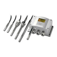
JUMO B 90.7023.1 Operating Instructions Manual (179 pages)
Transducers for Humidity and Temperature for industrial applications
Brand:
JUMO
| Category:
Measuring Instruments
| Size: 4 MB
Table of Contents
Table of Contents
3
Chapter 1 General Information
12
About this Manual
12
Contents of this Manual
12
General Safety Considerations
13
Feedback
13
Product Related Safety Precautions
14
ESD Protection
14
Regulatory Compliances
14
Transmitters with LAN or WLAN Interface
14
Transmitters with WLAN Interface
15
Recycling
16
Trademarks
16
License Agreement
16
Warranty
17
Chapter 2 Product Overview
18
Introduction to TRANSMITTER
18
Basic Features and Options
19
Structure of the Transmitter
20
Figure 1 Transmitter Body
20
Figure 2 Inside the Transmitter
21
Probe Options
22
Figure 3 Probe Options
22
Warmed Probe 907023/337
23
Chapter 3 Installation
24
Mounting the Housing
24
Standard Mounting Without Mounting Plate
24
Figure 4 Standard Mounting
24
Wall Mounting with Wall Mounting Kit
25
Figure 5 Mounting with Wall Mounting Kit
25
Figure 6 Dimensions of the Plastic Mounting Plate (MM/Inch)
25
Mounting with DIN Rail Installation Kit
26
Figure 7 Mounting with the DIN Rail Installation Kit
26
Pole Installation with Installation Kit for Pole or Pipeline
27
Figure 8 Vertical Pole
27
Figure 9 Horizontal Pole
27
Figure 10 Mounting with Metal Wall Mounting Plate
28
Figure 11 Dimensions of the Metal Mounting Plate (MM/Inch)
28
Mounting Rain Shield with Installation Kit
29
Panel Mounting Frame
29
Figure 12 Mounting the Rain Shield with the Installation Kit
29
Figure 13 Panel Mounting Frame
30
Figure 14 Panel Mounting Dimensions (MM/Inch)
30
Wiring
31
Cable Bushings
31
Figure 15 Cable Bushings
31
Grounding the Cables
32
Figure 16 Grounding the Screen of Electrical Cable
32
Grounding the Transmitter Housing
33
Signal and Power Supply Wiring
34
Figure 17 Screw Terminal Block on Motherboard
34
Connections to a 24 VAC Power Supply
35
Figure 18 Connections to 24 VAC Power Supply
36
Probe Mounting
37
Figure 19 Measurement Error at 100 %RH
37
Figure 20 Horizontal Mounting of Probe
38
General Instructions for Probes with a Cable
38
Figure 21 Vertical Mounting of Probe
39
907023/333 for Ducts and Tight Spaces
40
907023/334 for High Pressure and Vacuum Applications
40
Figure 22 907023/334 Probe
41
Figure 23 Tightening the Nut
41
907023/335 for High Temperatures
42
Figure 24 Cleaning of Tightening Cone
42
907023/337 for High Humidity Applications
43
Temperature Probe (Optional)
43
907023/338 for Pressurized Pipelines
43
Figure 25 907023/338 Probe
44
Figure 26 Sealing of Fitting Body into Process
44
Tightening the Clasp Nut
45
Figure 27 Tightening the Clasp Nut
45
Optional Modules
46
Power Supply Module
46
Figure 28 Power Supply Module
46
Installation
47
Warnings
48
Galvanic Isolation for Output
51
Third Analog Output
51
Figure 29 Galvanic Output Isolation Module
51
Figure 30 Third Analog Output
51
Figure 31 Third Analog Output Selection
52
Installation and Wiring
52
Relays
53
Installation and Wiring
53
Selecting the Activation State of the Relay
53
RS-422/485 Interface
55
Installation and Wiring
55
Figure 33 RS-485 Module
55
Figure 34 4-Wire RS-485 Bus
56
LAN Interface
57
WLAN Interface
58
Attaching the WLAN Antenna
59
Data Logger Module
59
Figure 37 Data Logger Module
61
8-Pin Connector
62
Figure 38 Wiring of Optional 8-Pin Connector
62
Chapter 4 Operation
63
Getting Started
63
Display/Keypad (Optional)
63
Basic Display
63
Graphic History
64
Figure 39 Basic Display
64
Figure 40 Graphical Display
64
Figure 41 Graphical Display with Data Logger
65
Menus and Navigation
66
Changing the Language
67
Figure 42 Main Menus
67
Rounding Setting
68
Display Backlight Setting
68
Display Contrast Setting
68
Keypad Lock (Key Guard)
68
Menu PIN Lock
69
Factory Settings
69
Display Alarms
70
Configuring a Display Alarm
70
Figure 43 Display Alarm Active
70
Figure 44 Display Alarms
71
Figure 45 Modifying an Alarm Limit
71
MI70 Link Program for Data Handling
72
Serial Line Communication
72
User Port Connection
73
Figure 46 Service Port Connector and User Port Terminal on Mother Board
73
Service Port Connection
74
Connection Cables
74
Figure 47 Connection Example between PC Serial Port and User Port
74
Installing the Driver for the USB Cable
75
Using the Service Port
75
LAN Communication
76
IP Configuration
76
Using Display/Keypad
77
Using Serial Line
78
Figure 48 Network Interface Menu
78
Figure 49 IP Configuration Menu
78
Wireless LAN Configuration
80
Using Display/Keypad
80
Figure 50 Wireless LAN Settings
81
Figure 51 Entering Network SSID
81
Figure 52 Selecting the Wireless Network Type
81
Using Serial Line
82
Telnet Settings
83
Figure 53 Web Configuration Interface for WLAN
84
Figure 54 Connecting Using Serial Interface
85
Figure 55 Connecting Using a Network
85
Figure 56 Hyper Terminal Serial Port Settings
86
Figure 57 Device Information on Display
102
Figure 58 Current/Voltage Switches of Output Modules
110
Figure 59 Measurement-Based Relay Output Modes
115
Figure 60 FAULT/ONLINE STATUS Relay Output Modes
117
Figure 61 Relay Indicators on Display
118
Figure 62 Decrease of Sensor Gain
126
Figure 63 Purge Buttons on Motherboard
128
Figure 64 Chemical Purge Settings
128
Figure 65 Performing Chemical Purge
129
Figure 66 Changing the Sensor
134
Figure 67 Error Indicator and Error Message
135
Figure 68 Adjustment and Purge Buttons
140
Figure 69 Adjustment Menu
140
Figure 70 Selecting Point 1 Reference Type
142
Figure 71 Accuracy over Temperature Range
150
Figure 72 Accuracy in Dewpoint Measurement
153
Figure 73 Transmitter Body Dimensions
160
Figure 74 WLAN Antenna Dimensions
161
Figure 75 907023/331 Probe Dimensions
161
Figure 76 907023/333 Probe Dimensions
162
Figure 77 907023/334 Probe Dimensions
162
Figure 78 907023/335 Probe Dimensions
163
Figure 79 907023/337 Probe Dimensions
163
Figure 80 907023/338 Probe Dimensions
164
Figure 81 Optional Temperature Probe Dimensions
164
Figure 82 Duct Mounting Installation Kit
165
Figure 83 Duct Mounting Installation Kit for T-Probe
166
Figure 84 Swagelok Installation Kit for RH-Probe
167
Figure 85 Swagelok Installation Kit for T-Probe
167
Figure 86 Cable Installation with Cable Gland
168
Figure 87 Probe Installation with Cable Gland
168
Figure 88 Vapor Tight Installation
169
Figure 89 Wall Mounting Installation
169
Figure 90 Climate Chamber Installation
170
Figure 91 Example of Installation through Roof
171
Figure 92 Installing the 907023/338 Probe through a Ball Valve Assembly
172
Figure 93 Meteorological Installation Kit for Outdoor Installation
174
Advertisement
Advertisement
Related Products
JUMO B70.1170.0
JUMO B 90.7027.1
Jumo B 707050.0
JUMO B 70.1050.0
JUMO B 70.7011.0
JUMO mTRON B 70.4025.4
JUMO mTRON B 70.4010.4
JUMO mTRON B 70.4015.4
JUMO B 709720.5
JUMO B 70.9040
JUMO Categories
Transmitter
Measuring Instruments
Controller
Thermostat
Voice Recorder
More JUMO Manuals
Login
Sign In
OR
Sign in with Facebook
Sign in with Google
Upload manual
Upload from disk
Upload from URL