
Subscribe to Our Youtube Channel
Related Manuals for Advantech AIMB-707


Summary of Contents for Advantech AIMB-707
- Page 1 User Manual AIMB-707 ® LGA1200 Intel Core i9/i7/i5/i3 ATX with Dual Display, M.2, SATA 3.0, USB 3.2, and DDR4...
- Page 2 No part of this manual may be reproduced, copied, translated or transmitted in any form or by any means without the prior written permission of Advantech Co., Ltd. Information provided in this manual is intended to be accurate and reliable. How- ever, Advantech Co., Ltd.
- Page 3 Whether your new Advantech equipment is destined for the labo- ratory or the factory floor, you can be assured that your product will provide the reliability and ease of operation for which the name Advantech has come to be known.
- Page 4 Caution! There is a danger of a new battery exploding if it is incorrectly installed. Do not attempt to recharge, force open, or heat the battery. Replace the battery only with the same or equivalent type recommended by the man- ufacturer. Discard used batteries according to the manufacturer's instructions. AIMB-707 User Manual...
- Page 5 Because of Advantech’s high quality-control standards and rigorous testing, most of our customers never need to use our repair service. If an Advantech product is defec- tive, it will be repaired or replaced at no charge during the warranty period. For out- of-warranty repairs, you will be billed according to the cost of replacement materials, service time and freight.
- Page 6 It should be free of marks and scratches and in perfect working order upon arrival. As you unpack the AIMB-707, check it for signs of ship- ping damage. (For example, damaged box, scratches, dents, etc.) If it is damaged or it fails to meet the specifications, notify our service department or your local sales representative immediately.
-
Page 7: Table Of Contents
Table 1.10:PCIe SMBus connection setting for clock (SMB1) and data (SMB2) ............. 11 System Memory ..................11 1.10 Memory Installation Procedures.............. 11 Chapter Connecting Peripherals ....13 Introduction ..................... 14 Parallel Port (LPT1)................. 14 LAN Port (LAN1, LAN2) and USB Port (USB3C1, USB3C2, USB3C3, AIMB-707 User Manual... - Page 8 PCIe x4 Expansion Slot (PCIE2 ~ PCIE3) ..........23 2.18 Auxiliary 8-pin Power Connector (ATX12V1).......... 23 2.19 Low Pin Count Connector (LPC1)............24 Table 2.3: Advantech LPC Module List ........24 2.20 GPIO Connector (GPIO1) ............... 24 2.21 SMBus Connector (SMBUS1)..............25...
- Page 9 Introduction ..................... 72 Installation ....................72 Chapter Configuration......73 Introduction ..................... 74 Features ....................74 Installation ....................74 Windows Driver Setup................74 Chapter HD Audio ..........75 Introduction ..................... 76 Installation ....................76 Appendix A Programming the Watchdog Timer..77 AIMB-707 User Manual...
- Page 10 Table B.24:SMBus Connector (SMBUS1) ........94 B.22 Front Panel Audio Connector (FPAUD1) ..........94 Table B.25:Front Panel Audio Connector (FPAUD1) ....94 B.23 Watchdog Timer Output and HW Monitor Alarm (JWDT1+JOBS1)..95 Table B.26:Watchdog Timer Output and HW Monitor Alarm AIMB-707 User Manual...
- Page 11 (JWDT1+JOBS1)............95 AIMB-707 User Manual...
- Page 12 AIMB-707 User Manual...
-
Page 13: Chapter 1 Hardware Configuration
Chapter Hardware Configuration... -
Page 14: Introduction
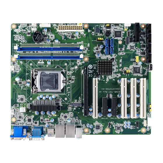
2 GB or above system memory is installed. AIMB-707 is equipped with one PCIe x16 (Gen 3), two PCIe x4 (Gen 3), and four PCI slots. Dual display interfaces are provided, enabling users to connect monitors to the onboard VGA and the DVI-D port at the same time (DVI-D only for G2 sku). -
Page 15: Memory
LPC: One LPC connector to support optional Advantech LPC modules, such as PCA-TPM-00B1E, PCA-COM232-00A1E, PCA-COM485-00A1E, etc. GPIO: AIMB-707 supports 8-bit GPIO from super I/O for general purpose con- trol application. Note! AIMB-707 is not equipped with PS/2 connector for keyboard/mouse. -
Page 16: Mechanical And Environmental Specifications
Jumpers and Connectors Connectors on the AIMB-707 motherboard link it to external devices such as hard disk drives and a keyboard. In addition, the board has a number of jumpers that are used to configure your system for your application. - Page 17 ATX 12 V auxiliary power connector (for CPU) EATXPWR1 ATX 24-pin main power connector (for system) SPDIF_OUT1 SPDIF audio out pin header GPIO1 8 bit GPIO from super I/O SMBUS1 SMBus connector from PCH FPAUD1 Front panel audio connector LPC1 Low pin count connector AIMB-707 User Manual...
-
Page 18: Board Layout: Jumper And Connector Locations
VGA1 COMD1 USB3C2 LAN1 COMD2 DVI1 AUDIO1+AUDIO2 USB3C1 Figure 1.1 Jumper and Connector Locations AUDIO1+AUDIO2 VGA1 COMD1 LAN1 LAN2 USB3C3 USB3C2 DVI1 COMD2 USB3C1 AIMB-707G2-00A1 AUDIO1+AUDIO2 VGA1 COMD1 LAN1 USB3C3 COMD2 USB3C1 AIMB-707VG-00A1 Figure 1.2 I/O connectors AIMB-707 User Manual... -
Page 19: Block Diagram
Caution! There is a danger of a new battery exploding if it is incorrectly installed. Do not attempt to recharge, force open, or heat the battery. Replace the battery only with the same or equivalent type recommended by the man- ufacturer. Discard used batteries according to the manufacturer’s instructions. AIMB-707 User Manual... -
Page 20: Jumper Settings
1.8.3 Watchdog timer output and OBS alarm (JWDT1+JOBS1) The AIMB-707 contains a watchdog timer that will reset the CPU. This feature means the AIMB-707 will recover from a software failure or an EMI problem. The JWDT1 jumper settings control the outcome of what the computer will do in the event the watchdog timer is tripped. -
Page 21: Atx/At Mode Selection (Pson1)
USB ports (JUSB_1) and onboard USB ports (JUSB_2) AIMB-707 allows users to set USB power between +5 V_DUAL and +5 V. When the jumper is set as +5 V, the board doesn't support wake up from S3 via keyboard or mouse. -
Page 22: Com3 Rs-232/422/485 Jumper Setting (Jsetcom3)
If JFV1 is set to enable, a dummy monitor on the VGA port is created to prevent the onboard graphics from being switched off while no physical monitors are connected. This function is useful when you control the AIMB-707 via remote KVM (such as Intel® AMT) and do not intend to connect any monitors. -
Page 23: Pcie Smbus Connection Setting For Clock (Smb1) And Data (Smb2)
* default setting System Memory AIMB-707 has two 288-pin memory sockets for DDR4 2400/2666/2933 memory modules with maximum capacity of 64 GB (Maximum 32 GB for each DIMM). The motherboard supports non-ECC unbuffered DIMMs (UDIMMs) and does NOT sup- port registered DIMMs (RDIMMs). - Page 24 AIMB-707 User Manual...
-
Page 25: Chapter 2 Connecting Peripherals
Chapter Connecting Peripherals... -
Page 26: Introduction
Parallel Port (LPT1) LPT1 The parallel port is normally used to connect the motherboard to a printer. The AIMB- 707 includes an onboard parallel port, accessed through a 25-pin flat-cable connec- tor, LPT1. AIMB-707 User Manual... -
Page 27: Lan Port (Lan1, Lan2) And Usb Port
1000Base-T operation. VG sku provides single GbE LAN only. The AIMB-707 provides up to 10 x USB ports. USB2A1, USB2A2, and USB2H1 are USB 2.0 ports supporting transmission rates up to 480 Mbps. USB3C1, USB3C2, and USB3C3 are USB 3.2 Gen 1 ports supporting transmission rates up to 5 Gbps. -
Page 28: Vga Connector (Vga1) And Dvi-D Connector (Dvi1)
COMD1 COMD2 The AIMB-707 G2 sku offers six serial ports (two on the rear panel and four onboard). COM3 can be configured as RS-232/422/485 by jumper settings (see Chapter 1) and BIOS selection (see Chapter 3). These ports can connect to a serial mouse, printer or communications network. -
Page 29: External Keyboard/Mouse Connector (Kbms1)
PCI slot. Therefore, one expansion slot on the motherboard will be occupied. CPU and System Fan Connector (CPUFAN1, SYSFAN1 ~ SYSFAN3) SYSFAN1 SYSFAN3 CPUFAN1 SYSFAN2 If a fan is used, this connector supports cooling fans that draw up to 500 mA (6 W). AIMB-707 User Manual... -
Page 30: Front Panel Connector (Jfp1, Jfp2, Jfp3)
AIMB-707 conditionally supports Advantech’s SAB-2000 module for providing infor- mation about the system fan speed and system temperature. When installing SAB- 2000 module on AIMB-707, please connect it to pins 8 and 11 of JFP2. 2.8.5 ATX Soft Power Switch (JFP1 pins 3, 6) If your computer case is equipped with an ATX power supply, you should connect the power on/off button on your computer case to pins 3 and 6 of JFP1. -
Page 31: Reset Connector (Jfp1 Pins 9, 12)
Mic In can be connected to a microphone. 2.10 8-pin Alarm Board Connector (VOLT1) VOLT1 VOLT1 connects to the alarm board on the Advantech chassis. The alarm board gives warnings if a power supply or fan fails, chassis overheats, or the backplane malfunctions. AIMB-707 User Manual... -
Page 32: Case Open Connector (Jcase1)
The default function is disabled and pins 1-2 is bridged by a jumper cap. 2.12 Front Panel LAN Indicator Connector (LANLED1) LANLED1 Table 2.2: Front Panel LAN Indicator Connector LAN Mode Indicator LAN Link ON LAN Active Flash LAN Link Off AIMB-707 User Manual... -
Page 33: Socket (Nvme1)
2.13 M.2 Socket (NVME1) NVME1 The AIMB-707 G2 sku is equipped with one M.2 socket to support up to PCIe x2 M- key 2280 type storage devices. A screw to fasten the device is already installed on the nut. 2.14... -
Page 34: Pci Slot (Pci1 ~ Pci4)
PCI2 PCI1 The AIMB-707 provides four 32-bit / 33 MHz PCI slots. 2.16 PCIe x16 Expansion Slot (PCIE1) PCIE1 The AIMB-707 provides a PCIe x16 slot for users to install an add-on peripheral card for extension requirements. AIMB-707 User Manual... -
Page 35: Pcie X4 Expansion Slot (Pcie2 ~ Pcie3)
2.17 PCIe x4 Expansion Slot (PCIE2 ~ PCIE3) PCIE3 PCIE2 The AIMB-707 offers two PCIe x4 slots for users to install add-on cards for extension requirements. PCIE2 and PCIE3 are PCIe x1 link. 2.18 Auxiliary 8-pin Power Connector (ATX12V1) ATX12V1 To ensure that enough power is supplied to the CPU, one auxiliary 8-pin power con- nector is available on the AIMB-707. -
Page 36: Low Pin Count Connector (Lpc1)
2.19 Low Pin Count Connector (LPC1) LPC1 LPC connector on AIMB-707 is reserved for optional Advantech LPC modules. Table 2.3: Advantech LPC Module List Description PCA-TPM-00B1E TPM 2.0 LPC module PCA-COM232-00A1E 4-port RS-232 LPC module PCA-COM485-00A1E 4-port RS-422/485 LPC module 2.20... -
Page 37: Smbus Connector (Smbus1)
2.21 SMBus Connector (SMBUS1) SMBUS1 AIMB-707 User Manual... - Page 38 AIMB-707 User Manual...
-
Page 39: Bios Operation
Chapter BIOS Operation... -
Page 40: Introduction
The Setup Utility uses a number of menus for making changes and turning specific features on or off. This chapter describes the basic nav- igation of the AIMB-707 setup screens. Figure 3.1 Main setup screen AMI’s BIOS ROM has a built-in Setup program that allows users to modify the basic... -
Page 41: Entering Bios Setup
System Date using the <Arrow> keys. Enter new values through the keyboard. Press the <Tab> key or the <Arrow> keys to move between fields. The date must be entered in MM/DD/YY format. The time must be entered in HH:MM:SS format. AIMB-707 User Manual... -
Page 42: Advanced Bios Features Setup
3.2.2 Advanced BIOS Features Setup Select the Advanced tab from the AIMB-707 setup screen to enter the Advanced BIOS setup screen. You can select any of the items in the left frame of the screen, such as CPU configuration, to go to the sub menu for that item. You can display an Advanced BIOS Setup option by highlighting it using the <Arrow>... - Page 43 3.2.2.1 Platform Misc Configuration Figure 3.4 Platform Misc Configuration Platform Misc Configuration – Native PCIE Enable PCI Express Native Support Enable/Disable. AIMB-707 User Manual...
- Page 44 Hardware Prefetcher is a technique that fetches instructions and/or data from memory into the CPU cache memory well before the CPU needs it to improve the load-to-use latency. You may choose to "Enable or Disable" it. AIMB-707 User Manual...
- Page 45 "Enable or Disable" utilization of additional hardware capabilities provided by Intel Trusted Execution Technology. Changes require a full power cycle to take effect. Rest AUX Content Reset TPM AUX content. TXT may not be functional after AUX content gets reset. AIMB-707 User Manual...
- Page 46 Figure 3.6 Power & Performance Boot Performance Select the performance state that the BIOS will set before OS handoff. Intel® Speedstep™ Allows more than two frequency ranges to be supported. Turbo Mode "Enable or Disable" processor turbo mode. AIMB-707 User Manual...
- Page 47 C states Intel® C states setting for power saving. 3.2.2.4 PCH-FW Configuration Figure 3.7 PCH-FW Configuration PCH-FW Version PCH-FW page shows Intel® ME FW information. Firmware Update Configuration AIMB-707 User Manual...
- Page 48 Figure 3.8 Firmware Update Configuration – ME FW Image Re-flash "Enable or Disable" ME firmware image re-flash function. 3.2.2.5 Trusted Computing Figure 3.9 TPM Settings AIMB-707 User Manual...
- Page 49 TPM Support "Enable or Disable" TPM Support. You can purchase Advantech LPC TPM mod- ule to enable TPM function. P/N: PCA-TPM-00B1E. 3.2.2.6 ACPI Settings Figure 3.10 ACPI Settings Enable ACPI Auto Configuration "Enable or Disable" ACPI auto configuration.
- Page 50 3.2.2.7 SMART Settings Figure 3.11 SMART Settings SMART Self Test "Enable or Disable" SMART Self Test on all HDDs during POST. AIMB-707 User Manual...
- Page 51 3.2.2.8 Super IO Configuration Figure 3.12 Super IO Configuration Figure 3.13 Serial Port 1 Configuration AIMB-707 User Manual...
- Page 52 Figure 3.14 Serial Port 2 Configuration Figure 3.15 Parallel Port Configuration AIMB-707 User Manual...
- Page 53 Parallel Port Configuration – Parallel Port "Enable or Disable" Parallel Port. – Change Settings Select an optimal setting for parallel port. – Device Mode Parallel port could be selected as "ECP and EPP 1.9 Mode" or other settings. AIMB-707 User Manual...
- Page 54 CPUFAN1 Smartfan Setting "Enable or Disable" CPUFAN1 Mode to SMART FAN setting. SYSFAN1/SYSFAN3 Smartfan Setting "Enable or Disable" SYSFAN1/SYSFAN3 Mode to SMART FAN setting. SYSFAN2 Smartfan Setting "Enable or Disable" SYSFAN2 Mode to SMART FAN setting. AIMB-707 User Manual...
- Page 55 3.2.2.10 Second Super IO Configuration Figure 3.17 Second Super IO Configuration AIMB-707 G2 sku supports 2nd super IO for COM 3~6. This page of BIOS menu is to set respective serial port configuration. Figure 3.18 Serial Port 3 Configuration AIMB-707 User Manual...
- Page 56 When serial port 3 (connector COM3) is set to RS-232, RS-422, or RS-485 via jumper JSETCOM3, this BIOS item should be selected as its correspond- ing one "RS-232 or RS-485 (Half Duplex) or RS-422 (Full Duplex)". Default for this Device Mode is "RS-232". Figure 3.19 Serial Port 4 Configuration AIMB-707 User Manual...
- Page 57 Figure 3.20 Serial Port 5 Configuration Figure 3.21 Serial Port 6 Configuration AIMB-707 User Manual...
- Page 58 Select an optimal setting for serial port 6. 3.2.2.11 S5 RTC Wake Settings Figure 3.22 S5 RTC Wake Settings Wake system with Fixed Time "Enable or Disable" System wake on alarm event. The system will wake on the hr:min:sec specified. AIMB-707 User Manual...
- Page 59 3.2.2.12 Serial Port Console Redirection Figure 3.23 Serial Port Console Redirection Figure 3.24 Legacy Console Redirection Settings AIMB-707 User Manual...
- Page 60 Select a COM port to display redirection of Legacy OS and Legacy OPROM Messages. Serial Port for Out-of-Band Management/ Windows Emergency Manage- ment services (EMS) – Console Redirection Settings Console Redirection "Enable or Disable". 3.2.2.13 Intel® TXT Information Figure 3.25 Intel® TXT Information AIMB-707 User Manual...
- Page 61 Hub descriptor. Mass Storage Devices Mass storage device emulation type. "Auto" enumerates device according to their media format. Optical drives are emulated as "CD-ROM", drives with no media will be emulated according to a drive type. AIMB-707 User Manual...
- Page 62 3.2.2.15 Network Stack Configuration Figure 3.27 Network Stack Configuration Network Stack "Enable or Disable" UEFI Network Stack. 3.2.2.16 CSM Configuration Figure 3.28 CSM Configuration AIMB-707 User Manual...
- Page 63 UEFI mode, make sure to select "Enabled" to allow non-UEFI boot mode before installing the graphic card to turn on the computer. 3.2.2.17 NVMe Configuration Figure 3.29 NVMe Configuration NVMe Configuration NVMe M.2 storage device is supported. AIMB-707 User Manual...
-
Page 64: Chipset
3.2.3 Chipset Figure 3.30 Chipset This page details information of the chipset on AIMB-707. AIMB-707 User Manual... - Page 65 Figure 3.31 System Agent (SA) Configuration VT-d "Enable or Disable" VT-d function. Above 4GB MMIO BIOS assignment "Enable or Disable" above 4GB MemoryMappedIO BIOS assignment. IPU Device (B0:D5:F0) "Enable or Disable" SA IPU device. AIMB-707 User Manual...
- Page 66 3.2.3.2 Memory Configuration Figure 3.32 Memory Configuration Maximum Memory Frequency Maximum memory frequency selections in MHz. AIMB-707 User Manual...
- Page 67 Set Internal Graphics to "Auto", "Disable" or "Enable". “Auto" will disable internal graphics when a GPU card is installed. If GPU and internal graphics outputs are required at the same time, set this item to "Enable". AIMB-707 User Manual...
- Page 68 3.2.3.4 PEG Port Configuration Figure 3.34 PEG Port Configuration Figure 3.35 PEG Port Feature Configuration Enable Root Port "Enable or Disable" the root port. Max Link speed Configure PEG 0:1:0 max speed. AIMB-707 User Manual...
- Page 69 "Enable and Disable" PowerOn by Modem Restore AC Power Loss Behavior when recovering from AC power loss: "S0" (power on), "S5" (power off), or "Last State". PCIE Device Initial Delay Users can set seconds to delay PCIE device initial time. AIMB-707 User Manual...
- Page 70 PCI Express Configuration Figure 3.37 PCI Express Configuration Figure 3.38 PCI Express Root Port PCI Express Root Port 5 "Enable or Disable" PCI Express Root Port. PCIe Speed Select "Auto, Gen1, Gen2, Gen3" for PCIe Speed. AIMB-707 User Manual...
- Page 71 Hot Plug "Enable or Disable" SATA hot-plug Spin Up Device "Enable or Disable" spin up device SATA Device Type Identifies that the SATA that is connected to a "Solid State Drive or Hard Disk Drive". AIMB-707 User Manual...
- Page 72 3.2.3.8 USB Configuration Figure 3.40 USB Configuration XHCI Compliance Mode Option to "Enable or Disable" XHCI compliance mode. Default is set to disable compliance mode. AIMB-707 User Manual...
- Page 73 "Enable or Disable" the PCH BIOS Lock Enable feature. Required to be enabled to ensure SMM protection of flash. Force unlock on all GPIO pads If Enabled, BIOS will force all GPIO pads to be in unlocked state. AIMB-707 User Manual...
- Page 74 3.2.3.10 HD Audio Configuration Figure 3.42 HD Audio Configuration HD Audio Control detection of the HD-Audio device. Disable = HDA will be unconditionally disabled. Enable = HDA will be unconditionally enabled. AIMB-707 User Manual...
-
Page 75: Security
Security Figure 3.43 Security Select Security Setup from the AIMB-707 Setup main BIOS setup menu. All Security Setup options, such as password protection are described in this section. To access the sub menu for the following items, select the item and press <Enter>. -
Page 76: Boot
Default state for the NumLock key during power on. Quiet Boot "Enable or Disable" Quiet Boot option. When enabled, BIOS logo will show in place of POST screen. Boot Option Priorities Set the boot order. AIMB-707 User Manual... -
Page 77: Save & Exit
Select Exit Discarding Changes from the Exit menu and press <Enter>. The fol- lowing message appears: Quit without saving? [Yes] [No] Select Yes to discard changes and exit. Discard Changes Select Discard Changes from the Exit menu and press <Enter>. AIMB-707 User Manual... - Page 78 AIMB-707 User Manual...
-
Page 79: Chapter 4 Chipset Software Installation Utility
Chapter Chipset Software Installation Utility... -
Page 80: Before You Begin
Before You Begin To facilitate the installation of the enhanced display drivers and utility software, read the instructions in this chapter carefully. The drivers for the AIMB-707 are located on the Advantech support website (http://www.advantech.com/support). Updates are provided via Service Packs from Microsoft. -
Page 81: Chapter 5 Integrated Graphic Device Setup
Chapter Integrated Graphic Device Setup... -
Page 82: Introduction
Before installing this driver, make sure the INF driver has been installed in your system. See Chapter 4 for information on installing the INF driver. Enter the Advantech support website, then search for product AIMB-707 and look for "Graphics" drivers. AIMB-707 User Manual... -
Page 83: Chapter 6 Intel® Me
Chapter Intel® ME... -
Page 84: Introduction
The Intel® ME software components that need to be installed depend on the sys- tem's specific hardware and firmware features. The installer detects the system's capabilities and installs the relevant drivers and applications. Installation Enter the Advantech support website, then search product AIMB-707. You can see "ME" driver inside. AIMB-707 User Manual... -
Page 85: Chapter 7 Lan Configuration
Chapter LAN Configuration... -
Page 86: Introduction
Introduction The AIMB-707 has dual Gigabit Ethernet LANs via dedicated PCI Express x1 lanes (Intel® I219LM (LAN1) and I211AT (LAN2)) that offer bandwidth of up to 500 MB/sec, eliminating network data bottlenecks and incorporating Gigabit Ethernet at 1000 Mbps. Features 10/100/1000Base-T Ethernet controller ... -
Page 87: Chapter 8 Hd Audio
Chapter HD Audio... -
Page 88: Introduction
Introduction AIMB-707 is equipped with Realtek ALC892 Audio chip. It provides "Line-out" & "Microphone" two ports for any related applications. Installation Enter the Advantech support website, then search product AIMB-707. You can see "Audio" driver inside. AIMB-707 User Manual... -
Page 89: Appendix A Programming The Watchdog Timer
Appendix Programming the Watchdog Timer... -
Page 90: Watchdog Timer Overview
The AIMB-707’s watchdog timer can be used to monitor system software operation and take corrective action if the software fails to function within the programmed period. This section describes the operation of the watchdog timer and how to pro- gram it. - Page 91 Unlock NCT6776D Select register of watchdog timer Enable the function of the watchdog timer Use the function of the watchdog timer Lock NCT6776D AIMB-707 User Manual...
-
Page 92: Example Programs
Mov al,07h ; Select registers of watchdog timer Out dx,al Inc dx in al,dx Or al,08h Out dx,al ;----------------------------------------------------------- Dec dx; Enable the function of watchdog timer Mov al,30h Out dx,al Inc dx Mov al,01h Out dx,al ;----------------------------------------------------------- AIMB-707 User Manual... - Page 93 Dec dx ; Enable the function of watchdog timer Mov al,30h Out dx,al Inc dx Mov al,01h Out dx,al ;----------------------------------------------------------- Dec dx ; Set minute as counting unit Mov al,0f5h Out dx, al Inc dx In al,dx Or al, 08h AIMB-707 User Manual...
- Page 94 Dec dx ; Enable watchdog timer to be reset by mouse Mov al,0f7h Out dx,al Inc dx In al,dx Or al,80h Out dx,al ;----------------------------------------------------------- Dec dx ; lock NCT6776D Mov al,0aah Out dx,al Enable watchdog timer to be reset by keyboard AIMB-707 User Manual...
- Page 95 Mov dx,2eh ; unlock NCT6776D Mov al,87h Out dx,al Out dx,al ;----------------------------------------------------------- Mov al,07h ; Select registers of watchdog timer Out dx,al Inc dx Mov al,08h Out dx,al ;----------------------------------------------------------- Dec dx ; Enable the function of watchdog timer Mov al,30h AIMB-707 User Manual...
- Page 96 Dec dx ; Generate a time-out signal Mov al,0f7h Out dx,al ;Write 1 to bit 5 of F7 register Inc dx In al,dx Or al,20h Out dx,al ;----------------------------------------------------------- Dec dx ; lock NCT6776D Mov al,0aah Out dx,al AIMB-707 User Manual...
-
Page 97: Appendix B I/O Pin Assignments
Appendix I/O Pin Assignments... -
Page 98: Parallel Port (Lpt1)
INITIALIZE# SELECT-PRINTER#/ DATA2 SELECT-IN# DATA3 DATA4 DATA5 DATA6 DATA7 ACK# BUSY PAPER-OUT/ PAPER-END SELECT LAN Port and USB 3.2 Port (LAN1, LAN2, USB3C1, USB3C2, USB3C3) LAN1_USB3C1, USB3C3 LAN2_USB3C2 Table B.2: LAN Port (LAN1, LAN2) Signal Signal DDTable AIMB-707 User Manual... -
Page 99: Usb 2.0 Port (Usb2A1, Usb2A2)
Table B.3: USB 3.2 Port (USB3C1, USB3C2, USB3C3) Signal STDA_SSRX. STDA_SSRX+ Shield GND_DRAIN STDA_SSTX. STDA_SSTX+ USB 2.0 Port (USB2A1, USB2A2) Table B.4: USB 2.0 Port (USB2A1, USB2A2) Signal USB 2.0 Header (USB2H1) Table B.5: USB 2.0 Header (USB2H1) Signal Signal AIMB-707 User Manual... -
Page 100: Vga Connector (Vga1)
TMDS Data 2/4 shield Hot plug detect TMDS data 0- DDC clock TMDS data 0+ DDC data TMDS data 0/5 shield TMDS Data 1- TMDS Data 1+ TMDS clock shield TMDS Data 1/3 shield TMDS clock+ TMDS clock- AIMB-707 User Manual... -
Page 101: And Com3 Interface (Comd1, Comd2, Com3 ~ Com6)
RS-232 and COM3 Interface (COMD1, COMD2, COM3 ~ COM6) Table B.8: RS-232 DB-9 Connector (COMD1, COMD2) Signal Table B.9: RS-232 Header (COM4 ~ COM6) Signal Table B.10: RS-232/422/485 Header (COM3) Signal 422/485 TX- 422/485 TX+ AIMB-707 User Manual... -
Page 102: External Keyboard/Mouse Connector (Kbms1)
(CPUFAN1, SYSFAN1 ~ SYSFAN3) Table B.12: CPU and System Fan Power Connector (CPUFAN1, SYSFAN1 ~ SYSFAN3) Signal +12 V SENSE B.10 Power LED and Keyboard Lock (JFP3) Table B.13: Power LED and Keyboard Lock (JFP3) Function POWER_LED+ AIMB-707 User Manual... -
Page 103: External Speaker Connector (Jfp2)
EXTENAL_SPK_2 INTENAL_SPK_P3 INTENAL_SPK_P4 B.12 HDD LED Connector (JFP2) Table B.15: HDD LED Connector (JFP2) Signal HDD_LED+ HDD_LED- B.13 SMBus Connector (JFP2) 8 11 Table B.16: SMBus Connector (JFP2) Signal SMB_SNMP_SDAT SMB_SNMP_SCLK B.14 ATX Soft Power Switch (JFP1) AIMB-707 User Manual... -
Page 104: Reset Connector (Jfp1)
8-pin Alarm Board Connector (VOLT1) Table B.19: 8-pin Alarm Board Connector (VOLT1) Signal Signal +5V_STBY +5 V +3.3 V -12 V -5 V +12 V B.17 Case Open Connector (JCASE1) Table B.20: Case Open Connector (JCASE1) Signal CASEOP AIMB-707 User Manual... -
Page 105: Front Panel Lan Indicator Connector (Lanled1)
Table B.22: Low Pin Count Connector (LPC1) Signal Signal CLK(24MHz) RESET# FRAME +3.3V SMB CLK SERIRQ SMB DAT +5V_DUAL B.20 GPIO Connector(GPIO1) Table B.23: GPIO Connector (GPIO1) Signal Signal GPIO0 GPIO4 GPIO1 GPIO5 GPIO2 GPIO6 GPIO3 GPIO7 +5V_DUAL_GPIO AIMB-707 User Manual... -
Page 106: Smbus Connector (Smbus1)
B.21 SMBus Connector (SMBUS1) Table B.24: SMBus Connector (SMBUS1) Signal SMB CLK SMB DAT B.22 Front Panel Audio Connector (FPAUD1) Table B.25: Front Panel Audio Connector (FPAUD1) Signal MIC-L MIC-R PRESENSE# LINE-R MIC-JD SENSE LINE-L LINE-JD AIMB-707 User Manual... -
Page 107: Watchdog Timer Output And Hw Monitor Alarm (Jwdt1+Jobs1)
B.23 Watchdog Timer Output and HW Monitor Alarm (JWDT1+JOBS1) Table B.26: Watchdog Timer Output and HW Monitor Alarm (JWDT1+JOBS1) Signal Signal SYSTEM RESET# ERROR_BEEP IR TXD IR RXD OBS_BEEP AIMB-707 User Manual... - Page 108 AIMB-707 User Manual...
- Page 109 AIMB-707 User Manual...
- Page 110 No part of this publication may be reproduced in any form or by any means, electronic, photocopying, recording or otherwise, without prior written permis- sion from the publisher. All brand and product names are trademarks or registered trademarks of their respective companies. © Advantech Co., Ltd. 2020...
Need help?
Do you have a question about the AIMB-707 and is the answer not in the manual?
Questions and answers