Advertisement
Quick Links
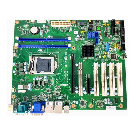
AIMB-705 LGA1151 Intel® Core™ i7/i5/i3 ATX with
Dual Display, DDR4, SATA III
Startup Manual
Packing List
Before you begin installing your card, please make sure
that the following items have been shipped:
• 1 Startup Manual
• 1 Driver CD (user's manual is included)
• 2 Serial ATA HDD data cables
• 1 Serial ATA HDD power cable
• 1 I/O port bracket
• 1 Warranty card
If any of these items are missing or damaged, please con-
tact your distributor or sales representative immediately.
Note:
Acrobat Reader is required to view any PDF
file. Acrobat Reader can be downloaded at:
www.adobe.com/Products/acrobat/readstep2.
html (Acrobat is a trademark of Adobe)
Specifications
Standard Functions
• CPU: LGA1151 6th and 7th Generation Intel® Core™ i7/
i5/i3/Pentium/Celeron
Note:
The Intel 7th generation processors only support
Windows 10 (64-bit).
• BIOS: AMI 128 Mb SPI BIOS
• Chipset: Intel® H110 chipset
• System memory: Up to 32 GB with two 288-pin
DIMM sockets. Supports dual channel non-ECC DDR4
1866/2133 MHz
Note:
Due to the inherent limitations of PC
architecture, the system may not fully detect
32 GB RAM when 32 GB RAM is installed
For more information on this and other Advantech
products, please visit our website at:
http://www.advantech.com
http://www.advantech.com/eplatform
For technical support and service, please visit our
support website at:
http://www.advantech.com/support
This manual is for the AIMB-705 series Rev. A1.
Part No. 2001070511
Printed in China
• SATA interface: Four on-board Serial ATAIII connectors
• PCIe and PCI slot: 1 PCIe x16 expansion slot, 1 PCIe
• LPC interface: Advantech-designed LPC connector
• Serial ports: Up to six serial ports: COM1, COM2 and
• Parallel port: One parallel port, which supports SPP/
• Keyboard/mouse connector: Supports standard PS/2
• Watchdog timer: 255 sec timer level intervals
• USB 3.0: Up to 4 (2 x pin header, 2 x rear I/O)
• USB 2.0: Up to 5 (2 x pin header, 2 x rear I/O, 1 x vertical
Graphic Interface
• Chipset: CPU integrated Intel HD graphics controller
• Display Memory: 1 GB maximum shared memory with 2
• Resolution:
Ethernet interface
• Interface: 10/100/1000 Mbps
• Controller: LAN1: Intel
Mechanical and Environmental
• Dimensions (L x W): 304.8 x 244 mm (12" x 9.6")
• Power supply voltage: +3.3 V, +5 V, +12 V, +5 Vsb
• Power Consumption:
• Operating temperature: 0 ~ 60° C (depending on CPU)
• Weight: 0.5 kg (weight of board)
2nd Edition
January 2017
Specifications (Cont.)
support data transmission rates up to 600 MB/s. All four
SATAIII ports support Advanced Host Controller Interface
(AHCI) technology
x4 expansion slot, 5 PCI slots 32-bit/33 MHz PCI 2.2
compliant
supports TPM module
COM4 ~ 6 are RS-232; COM3 is RS-232/422/485 with
jumper and BIOS options
EPP modes
keyboard and mouse
type A)
GB and above system memory installed
- Supports VGA up to 1920 x 1200 resolution @ 60 Hz
refresh rate
- Supports DVI up to 1920 x 1200 resolution @ 60 Hz
refresh rate
®
Intel Core Intel I7-6700 @ 3.4 GHz; DDR4 8 G x 2
Maximum: +3.3 V at 0.49 A, +5 V at 3.13 A, +12 V at 7.88
A, +5 Vsb at 0.08 A, -5 V at -0.07 A, -12 V at -0.07 A
AIMB-705 Startup Manual 1
I219-V; LAN2: Intel
I211-AT
®
Advertisement

Related Manuals for Advantech AIMB-705


Summary of Contents for Advantech AIMB-705
- Page 1 • Operating temperature: 0 ~ 60° C (depending on CPU) • Weight: 0.5 kg (weight of board) For technical support and service, please visit our support website at: http://www.advantech.com/support This manual is for the AIMB-705 series Rev. A1. Part No. 2001070511 2nd Edition January 2017 Printed in China...
- Page 2 EATXPWR1 system) SMBUS1 SM bus from PCH ATX 12 V auxiliary power connector ATX12V1 (for CPU) Low pin count connector for Advantech LPC1 TPM LPC and RS232 modules. DIMMA1 Channel A DIMM1 DIMMB1 Channel B DIMM1 JCMOS1/JME1: CMOS clear/ME update function...
- Page 3 SYSFAN2 PCIEX16_1 KBMS2 KBMS1 LANLED1 SPDIF_OUT1 AUDIO1 FPAUD1 LAN1_USB3_34 COM12 AUDIO2 VGA1+DVI1 LAN2_USB34 PWRSW RESET JFP1 SNMP & & HDDLED HDDLED SM_BUS JFP2 SPEAKER PWRLED & KEYLOCK JFP3 Figure 1: Board Layout: Jumper and Connector Locations AIMB-705 Startup Manual 3...
Need help?
Do you have a question about the AIMB-705 and is the answer not in the manual?
Questions and answers