
Related Manuals for Advantech AIMB-766


Summary of Contents for Advantech AIMB-766
- Page 1 User Manual AIMB-766 Socket LGA 775Core 2 Quad / Intel Core 2 Duo processor / Intel Pentium Dual Core / Celeron 1333 MHz FSB Industrial ATX Motherboard with PCIe/DDR2/ Dual GbE...
- Page 2 No part of this manual may be reproduced, copied, translated or transmitted in any form or by any means without the prior written permission of Advantech Co., Ltd. Information provided in this manual is intended to be accurate and reliable. How- ever, Advantech Co., Ltd.
- Page 3 Whether your new Advantech equipment is destined for the labo- ratory or the factory floor, you can be assured that your product will provide the reliability and ease of operation for which the name Advantech has come to be known.
-
Page 4: Declaration Of Conformity
Caution! There is a danger of a new battery exploding if it is incorrectly installed. Do not attempt to recharge, force open, or heat the battery. Replace the battery only with the same or equivalent type recommended by the man- ufacturer. Discard used batteries according to the manufacturer's instructions. AIMB-766 User Manual... - Page 5 1 GB DDR2 N E5108AHSE-8E-E (64x8) ELPIDA DDR2 2 GB DDR2 N E1108ACBG-8E-E (128x8) DDR2 Micron 7KE12 2 GB DDR2 N KVR667D2N5/2G NA D9HNL (128x8) Kingston ELPIDA (RoHS) DDR2 1 GB DDR2 N KVR800D2N5/1G NA E5108AHSE-8E-E (64x8) AIMB-766 User Manual...
- Page 6 Because of Advantech’s high quality-control standards and rigorous testing, most of our customers never need to use our repair service. If an Advantech product is defec- tive, it will be repaired or replaced at no charge during the warranty period. For out- of-warranty repairs, you will be billed according to the cost of replacement materials, service time and freight.
-
Page 7: Initial Inspection
It should be free of marks and scratches and in perfect working order upon receipt. As you unpack the AIMB-766, check it for signs of ship- ping damage. (For example, damaged box, scratches, dents, etc.) If it is damaged or it fails to meet the specifications, notify our service department or your local sales representative immediately. - Page 8 AIMB-766 User Manual viii...
-
Page 9: Table Of Contents
Board Layout: Jumper and Connector Locations........8 Figure 1.1 Jumper and Connector Locations....... 8 Figure 1.2 I/O connectors ............8 AIMB-766 Block Diagram................9 Figure 1.3 AIMB-766 Block Diagram ........... 9 Safety Precautions .................. 10 Jumper Settings ..................11 1.8.1 How to set jumpers .............. - Page 10 Clear NVRAM ................56 3.8.2 Plug and Play O/S ..............56 3.8.3 PCI Latency Timer ..............56 Boot Settings................... 57 Figure 3.17Boot Setup Utility............57 Figure 3.18Boot Setting Configuration ........57 3.9.1 Boot settings Configuration............58 3.10 Security Setup..................58 AIMB-766 User Manual...
- Page 11 Appendix B I/O Pin Assignments......91 IDE Hard Drive Connector (IDE1) ............92 Table B.1: IDE hard drive connector (IDE1) ......92 Floppy Drive Connector (FDD1).............. 93 Table B.2: Floppy drive connector (FDD1) ........ 93 Parallel Port (LPT1)................. 94 AIMB-766 User Manual...
- Page 12 Table B.27:System I/O ports............. 104 B.28 DMA Channel Assignments ..............104 Table B.28:DMA channel assignments........104 B.29 Interrupt Assignments ................105 Table B.29:Interrupt assignments..........105 B.30 1st MB Memory Map................105 Table B.30:1st MB memory map ..........105 AIMB-766 User Manual...
-
Page 13: Chapter 1 Hardware Configuration
Chapter Hardware Configuration... -
Page 14: Introduction
AIMB-766 the idea platform for industrial networking applications. By using the Intel ICH9 DO chipset, the AIMB-766 offers four 32-bit, 33 MHz PCI slots; two PCIe x1 slot, one PCIe x16 slot and a variety of features such as 6 on- board SATA II interfaces (bandwidth = 300 MB/s) with software for RAID 0, 1, 10 and 5;... -
Page 15: Features
High Performance I/O Capability: Dual/single Gigabit LAN via PCIe x1 bus, 4 PCI 32-bit/33MHz PCI slots, 6 SATA2 connectors and 12 USB 2.0 ports. Standard ATX form factor with industrial features: AIMB-766 provides indus- trial features like long product life, reliable operation under wide temperature range, watchdog timer, CMOS backup functions, etc. -
Page 16: Specifications
CPU coolers for high-speed CPUs in 2U chassis or in high-temperature environments Note! Advantech certifies two LGA775 CPU cooler solutions. Both coolers are capable of keeping the temperature of 95W-thermal-spec CPUs within ° specification under environmental temperatures of 55 C without a chas- °... -
Page 17: Input/Output
Maximum: +5 V at 3.58 A, +3.3 V at 2.86 A, +12 V at 3.52 A, +5 Vsb at 0.74 A, -12 V at 0.02 A (Intel Core 2 Quad9300 2.5 GHz (1333 MHz FSB), 4 x 1 GB DDR2 800 SDRAM) Board size: 304.8 x 228.6 mm (12" x 9.6") Board weight: 0.5 kg (1.68 lb) AIMB-766 User Manual... -
Page 18: Jumpers And Connectors
Jumpers and Connectors Connectors on the AIMB-766 motherboard link it to external devices such as hard disk drives and a keyboard. In addition, the board has a number of jumpers that are used to configure your system for your application. - Page 19 PCI2 PCI slot 2 PCI3 PCI slot 3 PCI4 PCI slot 4 DIMMA1 Channel A DIMM1 DIMMA2 Channel A DIMM2 DIMMB1 Channel B DIMM1 DIMMB2 Channel B DIMM2 SPI_CN1 Update BIOS pin header TPM_SLOT1 TPM2.0 Module connector AIMB-766 User Manual...
-
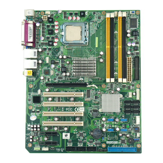
Page 20: Board Layout: Jumper And Connector Locations
Board Layout: Jumper and Connector Locations JFP3 JFP2 JFP1 JWDT1 JOBS1 Figure 1.1 Jumper and Connector Locations Figure 1.2 I/O connectors AIMB-766 User Manual... -
Page 21: Aimb-766 Block Diagram
AIMB-766 Block Diagram Figure 1.3 AIMB-766 Block Diagram AIMB-766 User Manual... -
Page 22: Safety Precautions
Caution! There is a danger of a new battery exploding if it is incorrectly installed. Do not attempt to recharge, force open, or heat the battery. Replace the battery only with the same or equivalent type recommended by the man- ufacturer. Discard used batteries according to the manufacturer’s instructions. AIMB-766 User Manual... -
Page 23: Jumper Settings
1.8.2 CMOS clear (CMOS1) The AIMB-766 motherboard contains a jumper that can erase CMOS data and reset the system BIOS information. Normally this jumper should be set with pins 1-2 closed. If you want to reset the CMOS data, set J1 to 2-3 closed for just a few sec- onds, and then move the jumper back to 1-2 closed. -
Page 24: Watchdog Timer Output (Jwdt1)
1.8.3 Watchdog timer output (JWDT1) The AIMB-766 contains a watchdog timer that will reset the CPU. This feature means the AIMB-766 will recover from a software failure or an EMI problem. The JSETCOM2 jumper settings control the outcome of what the computer will do in the event the watchdog timer is tripped. -
Page 25: System Memory
1.11 Cache Memory The AIMB-766 supports a CPU with one of the following built-in full speed L2 caches: 6 MB for Core 2 Quad 4 MB for Core 2 Duo 1 MB for Pentium®... -
Page 26: Processor Installation
1.12 Processor Installation The AIMB-766 is designed for Intel Core 2 Quad, Core 2 Duo, Pentium dual-core, Celeron D processors. Pull the bar besides the CPU socket outward and lift it. Align the triangular marking on the processor with the cut edge of the socket. -
Page 27: Pci Bus Routing Table
Put back the socket cap and press down the bar to fix it. 1.13 PCI Bus Routing Table PCI1 PCI2 PCI3 PCI4 PCI slot INT AIMB-766 User Manual... - Page 28 AIMB-766 User Manual...
-
Page 29: Chapter 2 Connecting Peripherals
Chapter Connecting Peripherals... -
Page 30: Introduction
Primary (IDE1) IDE Connector You can attach up to one IDE (Integrated Drive Electronics) drive to the AIMB-766’s built-in controller. Wire number 1 on the cable is red or blue and the other wires are gray. Connect one end to connector IDE1 on the motherboard. -
Page 31: Floppy Drive Connector (Fdd1)
Floppy Drive Connector (FDD1) You can attach up to two floppy disk drives to the AIMB-766’s onboard controller. You can use 3.5" (720 KB, 1.44 MB) drives. The motherboard comes with a 34-pin daisy-chain drive connector cable. On one end of the cable is a 34-pin flat-cable connector. -
Page 32: Parallel Port (Lpt1)
Parallel Port (LPT1) The parallel port is normally used to connect the motherboard to a printer. The AIMB-766 includes an onboard parallel port, accessed through a 26-pin flat- cable connector, LPT1. AIMB-766 User Manual... -
Page 33: Usb Ports (Lan1_Usb12, Lan2_Usb34, Usb56, Usb78, Usb910 & Usb1112)
480 Mbps and fuse protection are supported. The USB interface can be disabled in the system BIOS setup. The AIMB-766 is equipped with one or two high-performance 1000 Mbps Ethernet LANs. They are supported by all major network operating systems. The RJ-45 jacks on the rear plate provide convenient or 1000Base-T operation. -
Page 34: Vga Connector (Vga1)
VGA Connector (VGA1) The AIMB-766 includes a VGA interface that can drive conventional CRT displays. VGA1 is a standard 15-pin D-SUB connector commonly used for VGA. Pin assign- ments for CRT connector VGA1 are detailed in Appendix B. AIMB-766 User Manual... -
Page 35: Serial Ports (Com1, Com2, Com3 & Com4)
COM2 COM3 COM4 The AIMB-766 offers two serial ports (one on the rear panel and one onboard). JP1 is used to select the RS 232/422/485 mode for COM2. These ports can connect to a serial mouse, printer or communications network. -
Page 36: Ps/2 Keyboard And Mouse Connector (Kbms1)
PS/2 Keyboard and Mouse Connector (KBMS1) Two 6-pin mini-DIN connectors (KBMS1) on the rear panel of the motherboard pro- vide PS/2 keyboard and mouse connections. AIMB-766 User Manual... -
Page 37: External Keyboard & Mouse (Kbms2)
External Keyboard & Mouse (KBMS2) There is also an extra onboard external keyboard and mouse connector on the moth- erboard. This gives system integrators greater flexibility in designing their systems. AIMB-766 User Manual... -
Page 38: Cpu Fan Connector (Cpufan1)
2.10 CPU Fan Connector (CPUFAN1) If a fan is used, this connector supports cooling fans that draw up to 500 mA (6 W). AIMB-766 User Manual... -
Page 39: System Fan Connector (Sysfan1 And Sysfan2)
2.11 System FAN Connector (SYSFAN1 and SYSFAN2) SYSFAN1 SYSFAN2 If a fan is used, this connector supports cooling fans that draw up to 500 mA (6 W). AIMB-766 User Manual... -
Page 40: Front Panel Connectors (Jfp1, Jfp2 & Jfp3)
2.12 Front Panel Connectors (JFP1, JFP2 & JFP3) There are several external switches and LEDs to monitor and control the AIMB-766. JFP3 JFP2 JFP1 2.12.1 Power LED and Keyboard Lock (JFP3) JFP3 is a 5-pin connector for the power LED. Refer to Appendix B for detailed infor- mation on the pin assignments. -
Page 41: Hdd Led Connector (Jfp2 Pins 2 & 4)
1 and 2 of JFP1. This connection enables you to turn your computer on and off. 2.12.5 Reset Connector (JFP1 pins 3 & 4) Many computer cases offer the convenience of a reset button. AIMB-766 User Manual... -
Page 42: Line Out, Mic In Connector (Audio1)
2.13 Line Out, Mic In Connector (AUDIO1) Line Out MIC In Line Out can be connected to external audio devices like speakers or headphones. Mic In can be connected to a microphone. AIMB-766 User Manual... -
Page 43: 8-Pin Alarm Board Connector (Volt1)
2.14 8-pin Alarm Board Connector (VOLT1) VOLT1 connects to the alarm board of Advantech chassis. These alarm boards give warnings if a power supply or fan fails; if the chassis overheats; or if the backplane malfunctions. AIMB-766 User Manual... -
Page 44: Case Open Connector (Jcase1)
2.15 Case Open Connector (JCASE1) JCASE1 is for chassis with a case open sensor. The buzzer on the motherboard sounds if the case is opened. AIMB-766 User Manual... -
Page 45: Front Panel Lan Indicator Connector (Lan_Led1)
2.16 Front Panel LAN Indicator Connector (LAN_LED1) Table 2.2: Front Panel LAN Indicator Connector LAN Mode Indicator G-LAN Link ON Green ON G-LAN Active Green Flash G-LAN Link Off Green OFF AIMB-766 User Manual... -
Page 46: Serial Ata Interface (Sata1, Sata2, Sata3, Sata4, Sata5 & Sata6)
Serial ATA Interface (SATA1, SATA2, SATA3, SATA4, SATA5 & SATA6) In addition to the IDE interface, the AIMB-766 features a high performance serial ATA interface (up to 300 MB/s) which eases cabling to hard drives with thin and long cables. AIMB-766VG-00A1E sku only support 4 SATA connectors. -
Page 47: Pci Slots (Pci 1 ~ Pci 4)
2.18 PCI Slots (PCI 1 ~ PCI 4) The AIMB-766 provides four 32-bit / 33 MHz PCI slots. Note! 64-bit PCI or PCI-X expansion cards installed in the PCI 2 slots will not fit because of the south bridge heat sink. If you want to use 64-bit PCI or PCI-X expansion cards, please install them in the PCI 1, PCI 3 or PCI 4 . -
Page 48: Pcie X16 Expansion Slot (Pciex16_1)
2.19 PCIe x16 Expansion Slot (PCIEX16_1) The AIMB-766 provides a PCIe x16 slot for users to install add-on VGA cards when their applications require higher graphics performance than the onboard graphics controller can provide. AIMB-766 User Manual... -
Page 49: Pciex1_1
2.20 PCIEX1_1 AIMB-766 User Manual... -
Page 50: Pciex1_2
2.21 PCIEX1_2 AIMB-766 User Manual... -
Page 51: Auxiliary 4-Pin Power Connector (Atx1)
The order part number of TPM module is 9680004525. 2.24 SPI Flash connector(SPI_CN1) SPI flash card pin header which can flash BIOS while AIMB-766 can not be power on and ensures platform integrity. AIMB-766 User Manual... - Page 52 AIMB-766 User Manual...
-
Page 53: Bios Operation
Chapter BIOS Operation... -
Page 54: Figure 3.1 Setup Program Initial Screen
The Setup program uses a number of menus for making changes and turning the special features on or off. This chapter describes the basic navigation of the AIMB-766 setup screens. Figure 3.1 Setup program initial screen AMI’s BIOS ROM has a built-in Setup program that allows users to modify the basic... -
Page 55: Entering Setup
BIOS supports your CPU. If there is no number assigned to the patch code, please contact an Advantech application engineer to obtain an up-to-date patch code file. This will ensure that your CPU’s system status is valid. -
Page 56: Main Setup
Date using the <Arrow> keys. Enter new values through the keyboard. Press the <Tab> key or the <Arrow> keys to move between fields. The date must be entered in MM/DD/YY format. The time must be entered in HH:MM:SS format. AIMB-766 User Manual... -
Page 57: Advanced Bios Features Setup
Advanced BIOS Features Setup Select the Advanced tab from the AIMB-766 setup screen to enter the Advanced BIOS Setup screen. You can select any of the items in the left frame of the screen, such as CPU Configuration, to go to the sub menu for that item. You can display an Advanced BIOS Setup option by highlighting it using the <Arrow>... -
Page 58: Cpu Configuration
Disabled. The Optimal and Fail-Safe default setting is Enabled. If Disabled is selected, the BIOS forces the XD feature flag to always return to 0. PECI You may choose to disable or enable the Platform Environment Control Interface function. AIMB-766 User Manual... -
Page 59: Ide Configuration
3.3.2 IDE Configuration Figure 3.6 IDE Configuration SATA Configuration This can be configured as Disabled or Enhanced. Configure SATA as This can be configured as IDE, RAID or AHCI. RAID will be activated by the ICH9DO only. AIMB-766 User Manual... -
Page 60: Super I/O Configuration
Floppy A Select the type of floppy drive connected to the system. We suggest you disable the floppy while installing Windows Vista without a floppy drive. Floppy B Select the type of floppy drive connected to the system. AIMB-766 User Manual... -
Page 61: Hardware Health Configuration
The system will shut down automatically under OS with ACPI mode, when the CPU temperature is over the selected setting. Hardware health event monitoring When the Hardware Health Function is enabled, the BIOS will display hardware health information. AIMB-766 User Manual... -
Page 62: Acpi Settings
ACPI Settings Figure 3.9 ACPI Settings Figure 3.10 General ACPI Configuration AIMB-766 User Manual... -
Page 63: General Acpi Configuration
3.4.1 General ACPI Configuration Suspend mode Select the ACPI state used for system suspend. Figure 3.11 Advanced ACPI Configuration 3.4.2 Advanced ACPI Configuration ACPI APIC support Include APIC table pointer to RSDT pointer list. AIMB-766 User Manual... -
Page 64: Figure 3.12South Bridge Acpi Configuration
Allows you to configure Intel's Energy lake power management technology. APIC ACPI SCI IRQ Enable/Disable APIC ACPI SCI IRQ. USB Device Wakeup From S3/S4 Enable/Disable USB Device Wakeup from S3/S4. High Performance Event Timer Enable/Disable High performance Event timer. AIMB-766 User Manual... -
Page 65: Apm Configuration
"former-STs" returns the system to the status before power failure. Throttle Slow Clock Ratio Select the Duty Cycle in Throttle mode. Resume On Ring: Disable/Enable RI wake event. Resume On LAN: Disable/Enable LAN PME wake event. Resume On RTC Alarm: Disable/Enable RTC wake event. AIMB-766 User Manual... -
Page 66: Figure 3.14Configure Remote Access Type And Parameters
Configure Remote Access Type and parameters Remote Access You can disable or enable the BIOS remote access feature here. This function is used to redirect the console from the serial port. The Optimal and Fail-Safe default setting is Disabled. AIMB-766 User Manual... -
Page 67: Trusted Computing
Trusted Computing This item allow you to set the TPM (Trusted Platform Module) features Select Enable/Disable (TPM 1.1/1.2) support in BIOS Figure 3.15 Trusted Computing AIMB-766 User Manual... -
Page 68: Advanced Pci/Pnp Settings
Advanced PCI/PnP Settings Select the PCI/PnP tab from the AIMB-766 setup screen to enter the Plug and Play BIOS Setup screen. You can display a Plug and Play BIOS Setup option by highlight- ing it using the <Arrow> keys. All Plug and Play BIOS Setup options are described in this section. -
Page 69: Boot Settings
Boot Settings Figure 3.17 Boot Setup Utility Figure 3.18 Boot Setting Configuration AIMB-766 User Manual... -
Page 70: Boot Settings Configuration
Security Setup Figure 3.19 Password Configuration Select Security Setup from the AIMB-766 Setup main BIOS setup menu. All Security Setup options, such as password protection and virus protection are described in this section. To access the sub menu for the following items, select the item and press <Enter>:... -
Page 71: Advanced Chipset Settings
3.11 Advanced Chipset Settings Figure 3.20 Advanced Chipset Settings Figure 3.21 North Bridge Configuration AIMB-766 User Manual... -
Page 72: North Bridge Chipset Configuration
DVMT model select Displays the active system memory mode. DVMT / FIXED Memory Specify the amount of DVMT / FIXED system memory to allocate for video memory. Boot display device Select boot display device at post stage. AIMB-766 User Manual... -
Page 73: Figure 3.23South Bridge Configuration
LAN1 Option-ROM: Enables or disables GbE LAN boot. LAN2 Controller: Enables or disables the LAN2 controller. LAN2 option ROM: HDA Controller: Enables or disables the HDA controller. SMBUS Controller: Enables or disables the SMBUS controller. ME subsystem configuration. AIMB-766 User Manual... -
Page 74: Figure 3.24South Bridge Chipset Configuration
Figure 3.24 South Bridge Chipset Configuration 3.11.3 ME Subsystem Configuration ME-HECI:Enable/disable ME-H ME-IDER:Enable/disable ME-IDER ME-KT: Enable/Disable ME-KT AIMB-766 User Manual... -
Page 75: Exit Option
Select Exit Discarding Changes from the Exit menu and press <Enter>. The fol- lowing message appears: Discard Changes and Exit Setup Now? [Ok] [Cancel] Select Ok to discard changes and exit. Discard Changes Select Discard Changes from the Exit menu and press <Enter>. AIMB-766 User Manual... -
Page 76: Load Optimal Defaults
3.12.3 Load Optimal Defaults The AIMB-766 automatically configures all setup items to optimal settings when you select this option. Optimal Defaults are designed for maximum system performance, but may not work best for all computer applications. In particular, do not use the Opti- mal Defaults if your computer is experiencing system configuration problems. -
Page 77: Chapter 4 Chipset Software Installation Utility
Chapter Chipset Software Installation Utility... -
Page 78: Before You Begin
Before you begin To facilitate the installation of the enhanced display drivers and utility software, read the instructions in this chapter carefully. The drivers for the AIMB-766 are located on the software installation CD. Note! Fiel are compressed. Do not attempt to install the drivers by copying the files manually. -
Page 79: Windows Xp Driver Setup
Insert the driver CD into your system's CD-ROM drive. You can see the driver folders items. Move the mouse cursor over the folder "INF". In INF folder, you can click "setup.exe" to complete the implement of the driver Click setup to execute program. AIMB-766 User Manual... - Page 80 AIMB-766 User Manual...
-
Page 81: Chapter 5 Vga Setup
Chapter VGA Setup... -
Page 82: Introduction
2048 x 1536 @ 75 MHz refresh, 350 MHz integrated 24-bit RAMDAC. AIMB-766 supports dual channels SDVO interface. It supports flat panels up to 1920 x 1200 @ 60 MHz or digital CRT/ HDTV at 1400 x 1050 @ 85 MHz. -
Page 83: Chapter 6 Lan Configuration
Chapter LAN Configuration... -
Page 84: Introduction
Introduction The AIMB-766 is designed with dual gigabit Ethernet controller- Intel 82556DM and Intel 82573L. The Intel® 82566DM Gigabit Ethernet Controller is a compact, single- port integrated physical layer device that connect to appropriate Intel® chipsets with an integrated Media Access Controller (MAC). The 82566DM supports Intel® Active Management Technology. -
Page 85: Win Xp Driver Setup (Lan)
Win XP Driver Setup (LAN) Insert the driver CD into your system's CD-ROM drive. Select the LAN folder then click the proper Lan driver for the OS. AIMB-766 User Manual... - Page 86 AIMB-766 User Manual...
-
Page 87: Chapter 7 Amt Setup
Chapter AMT Setup... -
Page 88: Intel Amt Overview
Intel AMT Overview AIMB-766 supports Intel Active Management Technology 3.0. The hardware and firmware based solution (ICH9 DO only, for AIMB-766G2-00A1E sku only) is pow- ered by the system auxiliary power plane to remotely monitor networked systems. Intel AMT stores hardware and software information in non-volatile memory. Built-in management provides out-of-band management capabilities, allowing remote dis- covery and repair of systems after OS failures or when a system is powered down. - Page 89 The following installation procedure is for Windows XP. Currently, Vista drivers are not available. You will see a welcome window. Click “Next” to continue the installation. Please click “Yes” to continue the installation. AIMB-766 User Manual...
- Page 90 Please click “Next” to continue the installation. Please click “Next” to continue the installation. AIMB-766 User Manual...
-
Page 91: Windows Xp Amt Me Driver Setup
Click “Finish” to complete the installation. Windows XP AMT ME Driver Setup Insert the driver CD into your system's CD-ROM drive. Select the AMT folder then click setup in LMS_SOL folder to install AMT ME driver. AIMB-766 User Manual... - Page 92 Please click “Yes” to continue the installation. Please click “Next” to continue the installation. AIMB-766 User Manual...
- Page 93 Please click “Next” to continue the installation. Click “Finish” to complete the installation. AIMB-766 User Manual...
- Page 94 AIMB-766 User Manual...
-
Page 95: Appendix A Programming The Watchdog Timer
Appendix Programming the Watchdog Timer... -
Page 96: Watchdog Timer Overview
The AIMB-766’s watchdog timer can be used to monitor system software operation and take corrective action if the software fails to function within the programmed period. This section describes the operation of the watchdog timer and how to pro- gram it. - Page 97 Unlock W83627DHG Select register of watchdog timer Enable the function of the watchdog timer Use the function of the watchdog timer Lock W83627DHG AIMB-766 User Manual...
-
Page 98: Example Programs
Mov al,08h Out dx,al ;----------------------------------------------------------- Dec dx ; Enable the function of watchdog timer Mov al,30h Out dx,al Inc dx Mov al,01h Out dx,al ;----------------------------------------------------------- Dec dx ; Set second as counting unit Mov al,0f5h Out dx,al AIMB-766 User Manual... - Page 99 Dec dx ; Set minute as counting unit Mov al,0f5h Out dx, al Inc dx In al,dx Or al, 08h Out dx,al ;----------------------------------------------------------- Dec dx ; Set timeout interval as 5 minutes and start counting Mov al,0f6h AIMB-766 User Manual...
- Page 100 Inc dx In al,dx Or al,80h Out dx,al ;----------------------------------------------------------- Dec dx ; lock W8362DHG Mov al,0aah Out dx,al Enable watchdog timer to be reset by keyboard ;----------------------------------------------------------- Mov dx,2eh ; unlock W83627DHG Mov al,87h Out dx,al Out dx,al AIMB-766 User Manual...
- Page 101 Mov al,07h ; Select registers of watchdog timer Out dx,al Inc dx Mov al,08h Out dx,al ;----------------------------------------------------------- Dec dx ; Enable the function of watchdog timer Mov al,30h Out dx,al Inc dx Mov al,01h Out dx,al ;----------------------------------------------------------- AIMB-766 User Manual...
- Page 102 Dec dx ; Generate a time-out signal Mov al,0f7h Out dx,al ;Write 1 to bit 5 of F7 register Inc dx In al,dx Or al,20h Out dx,al ;----------------------------------------------------------- Dec dx ; lock W83627DHG Mov al,0aah Out dx,al AIMB-766 User Manual...
-
Page 103: Appendix B I/O Pin Assignments
Appendix I/O Pin Assignments... -
Page 104: Ide Hard Drive Connector (Ide1)
DATA 15 SIGNAL GND DISK DMA REQUEST IO WRITE IO READ IO CHANNEL READY CSEL HDACKO* IRQ14 ADDR 1 PDIAG ADDR 0 ADDR 2 HARD DISK SELECT 0* HARD DISK SELECT 1* IDE ACTIVE* * low activity AIMB-766 User Manual... -
Page 105: Floppy Drive Connector (Fdd1)
Table B.2: Floppy drive connector (FDD1) Signal Signal FDHDIN* FDEDIN* INDEX* MOTOR 0* DRIVE SELECT 1* DRIVE SELECT 0* MOTOR 1* DIRECTION* STEP* WRITE DATA* WRITE GATE* TRACK 0* WRITE PROTECT* READ DATA* HEAD SELECT* DISK CHANGE* * low activity AIMB-766 User Manual... -
Page 106: Parallel Port (Lpt1)
Signal STROBE* AUTOFD* INIT* SLCTINI* ACK* BUSY SLCT * low activity USB Header (USB56, USB78, USB910 & USB1112) LAN1_USB12 LAN2_USB34 USB56 USB78 USB910 USB1112 Table B.4: USB Header (USB56,USB78,USB910) Signal Signal USB_VCC5 USB_VCC5 USB_D- USB_D- USB_D+ USB_D+ AIMB-766 User Manual... -
Page 107: Vga Connector (Vga1)
VGA Connector (VGA1) Table B.5: VGA Connector (VGA1) Signal Signal GREEN BLUE H-SYNC V-SYNC RS-232 Interface (COM1, COM2, COM3 & COM4) COM1 Table B.6: RS-232 Interface (COM1) Signal AIMB-766 User Manual... -
Page 108: Ps/2 Keyboard And Mouse Connector (Kbms1)
PS/2 Keyboard and Mouse Connector (KBMS1) Table B.7: Keyboard and Mouse Connector (KBMS1) Signal KB DATA KB VCC KB CLK External Keyboard Connector (KBMS2) Table B.8: External Keyboard Connector (KBMS2) Signal KB CLK KB DATA MS DATA MS CLK AIMB-766 User Manual... -
Page 109: Infrared (Ir) Connector (Jir1)
CPU/System Fan Power Connector (SYSFAN1/ SYSFAN2) Table B.10: Fan Power Connector (SYSFAN1/CHAFAN1) Signal +12 V DETECT B.11 Power LED and Keyboard Lock (JFP3) Table B.11: Power LED and Keyboard Lock (JFP3) Function LED power (+5 V) Ground #keylock Ground AIMB-766 User Manual... -
Page 110: External Speaker Connector (Jfp2)
External Speaker Connector (JFP2) Table B.12: External Speaker Connector (JFP2) Function Buzzer Buzzer Speaker out B.13 Reset Connector (JFP1) Table B.13: Reset Connector (JFP1) Signal RESET B.14 HDD LED Connector (JFP2) Table B.14: HDD LED Connector (JFP2) Signal IDE/SATA AIMB-766 User Manual... -
Page 111: Atx Soft Power Switch (Jfp1)
Table B.15: ATX Soft Power Switch (JFP1) Signal PWR-BTN B.16 H/W Monitor Alarm (JOBS1) Table B.16: H/W Monitor Alarm (JOBS1) Signal Error Beep OBS Beep alarm B.17 SM Bus Connector (JFP2) Table B.17: SM Bus Connector (JFP2) Signal SMB_DATA SMB_CLK AIMB-766 User Manual... -
Page 112: Usb/Lan Ports (Lan1_Usb12 And Lan2_Usb34)
Table B.18: USB Port Signal Signal VCC_DUAL Data0+ Data0- Table B.19: Giga LAN 10/100/1000 Base-T RJ-45 port Signal Signal MID0+ MID2+ MID0- MID2+ MID1+ MID3+ MID1- MID3+ B.19 Line Out, Mic IN Connector (AUDIO1) Line Out MIC In AIMB-766 User Manual... -
Page 113: Audio Input From Cd-Rom (Cdin1)
Table B.21: Audio Connector (FP AUDIO; FAUDIO1) Signal Signal MIC2_L Ground MIC2_R VCC3 LINEOUT2_R Ground FRONT_IO_JD LINEOUT2_L Ground B.22 8-pin Alarm Board Connector (VOLT1) Table B.22: 8-pin Alarm Board Connector (VOLT1) Signal Signal 5VSB VCC3 -12V +12V AIMB-766 User Manual... -
Page 114: Case Open Connector (Jcase1)
B.23 Case Open Connector (JCASE1) Table B.23: Case Open Connector (JCASE1) Signal CASEOP B.24 Front Panel LAN LED Connector (LAN_LED1) Table B.24: LAN LED Connector (LANLED1) Signal Signal LAN1_LINK/ACT LAN2_LINK/ACT 3VDUAL 3VDUAL LAN1_LINK1000 LAN2_LINK1000 LAN1_LINK100 LAN2_LINK100 3VDUAL AIMB-766 User Manual... -
Page 115: Spi_Cn1: Spi Fresh Card Pin Connector
Table B.25: SPI_CN1:SPI fresh card pin connector Signal Signal +F1_3V F1_SPI_CS#_Q F1_SPI_CLK_Q F1_SPI_MISO_Q F1_SPI_MOSI_Q B.26 TPM_SLOT1: TPM module connector Table B.26: TPM_SLOT1:TPM module connector Signal Signal SMB_ CLK FRAME# SMB_DATA REST LAD2 LAD3 LAD1 VCC3 LAD0 VCC3 SERIRQ# VCC3SB CLKRUN# SLPS3# AIMB-766 User Manual... -
Page 116: System I/O Ports
3D0-3DF Color/graphics monitor adapter 3F0-3F7 Diskette controller 3F8-3FF Serial port 1 B.28 DMA Channel Assignments Table B.28: DMA channel assignments Channel Function Available Available Floppy disk (8-bit transfer) Available Cascade for DMA controller 1 Available Available Available AIMB-766 User Manual... -
Page 117: Interrupt Assignments
1st MB Memory Map Table B.30: 1st MB memory map Addr. range (Hex) Device E0000h - FFFFFh BIOS CC000h - DFFFFh Unused C0000h - CBFFFh VGA BIOS A0000h - BFFFFh Video Memory 00000h - 9FFFFh Base memory AIMB-766 User Manual... - Page 118 No part of this publication may be reproduced in any form or by any means, electronic, photocopying, recording or otherwise, without prior written permis- sion of the publisher. All brand and product names are trademarks or registered trademarks of their respective companies. © Advantech Co., Ltd. 2008...
Need help?
Do you have a question about the AIMB-766 and is the answer not in the manual?
Questions and answers