
Related Manuals for Advantech AIMB-780


Summary of Contents for Advantech AIMB-780
- Page 1 User Manual AIMB-780 Intel® LGA1156 Core i7/i5/i3/ Pentium/Xeon ATX Motherboard with VGA/DVI, DDR3, 4 COM, Dual LAN...
- Page 2 No part of this manual may be reproduced, copied, translated or transmitted in any form or by any means without the prior written permission of Advantech Co., Ltd. Information provided in this manual is intended to be accurate and reliable. How- ever, Advantech Co., Ltd.
- Page 3 Whether your new Advantech equipment is destined for the labo- ratory or the factory floor, you can be assured that your product will provide the reliability and ease of operation for which the name Advantech has come to be known.
-
Page 4: Declaration Of Conformity
Caution! There is a danger of a new battery exploding if it is incorrectly installed. Do not attempt to recharge, force open, or heat the battery. Replace the battery only with the same or equivalent type recommended by the man- ufacturer. Discard used batteries according to the manufacturer's instructions. AIMB-780 User Manual... - Page 5 DDR3 N KVR1333D3N9/1G H5TQ1G83BFR H9C 928AK (128x8) hynix Apacer 4GB DDR3-1333 DDR3 N 78.B1GDE.AF1 H5TQ2G83AFR H9C 003AK KHX1333C7D3K2/ Kingston 2GB DDR3-1333 DDR3 N 128Mx8bit AIMB-780 Feature Comparison AIMB-780QG2 AIMB-780WG2 Chipset 3450 Memory Non-ECC Non-ECC/ECC SW RAID Optional Optional AIMB-780 User Manual...
- Page 6 It should be free of marks and scratches and in perfect working order upon receipt. As you unpack the AIMB-780, check it for signs of ship- ping damage. (For example, damaged box, scratches, dents, etc.) If it is damaged or it fails to meet the specifications, notify our service department or your local sales representative immediately.
-
Page 7: Table Of Contents
Board Layout: Jumper and Connector Locations........8 Figure 1.1 Jumper and Connector Locations....... 8 Figure 1.2 I/O connectors ............8 AIMB-780 Block Diagram................9 Figure 1.3 AIMB-780 Block Diagram ........... 9 Safety Precautions .................. 10 Jumper Settings ..................11 1.8.1 How to set jumpers .............. - Page 8 USB Configuration ..............55 Figure 3.18USB Configuration............ 55 Advanced PCI/PnP Settings ..............56 Figure 3.19PCI/PNP Setup (top) ..........56 Boot Settings................... 57 Figure 3.20Boot Setup Utility............57 Figure 3.21Boot Setting Configuration ........57 Security Setting..................58 AIMB-780 User Manual viii...
- Page 9 USB Header (USB56, USB78, USB910, USB1112 & USB1314) ... 87 Table B.3: USB Header (USB56,USB78,USB910,USB1112,USB1314)87 VGA Connector (VGA1) ................88 Table B.4: VGA Connector (VGA1) ........... 88 RS-232 Interface (COM3 & COM4) ............88 Table B.5: RS-232 Interface (COM1)......... 88 AIMB-780 User Manual...
- Page 10 Table B.24:System I/O ports............96 B.25 DMA Channel Assignments ..............96 Table B.25:DMA channel assignments........96 B.26 Interrupt Assignments ................97 Table B.26:Interrupt assignments..........97 B.27 1st MB Memory Map................97 Table B.27:1st MB memory map ..........97 AIMB-780 User Manual...
-
Page 11: Chapter 1 Hardware Configuration
Chapter Hardware Configuration... -
Page 12: Introduction
2 GB and above system memory installed. When higher graphics performance is needed, AIMB-780 provides a mainstream PCIe x16 expansion slot for add-on graphic cards. In addition, the AIMB-780 has a dual Gigabit Ethernet LAN via a dedicated PCIe x1 bus, which offers bandwidth of up to 500 MB/s, eliminating network bottlenecks. -
Page 13: Features
Automatically power on after power failure: It is often necessary to have an unattended system come back to operation when power resumes after a power failure. Advantech’s industrial motherboard allows users to set the system to power on automatically without pushing the power on button. -
Page 14: Specifications
ECC unbuffered DIMMs – AIMB-780WG2-00A1E(3450 Chipset): supports both ECC and non-ECC unbuffered DIMMs. Neither platforms support any memory configuration that mix non-ECC with ECC unbuffered DIMMs. AIMB-780 User Manual... -
Page 15: Input/Output
-12 V at 0.01 A (Intel Core i5 660 3.3GHz processor and C state is disable , 4 x 2 GB DDR3 Memory SDRAM) Board size: 304.8 x 228.6 mm (12" x 9.6") Board weight: 0.5 kg (1.68 lb) AIMB-780 User Manual... -
Page 16: Jumpers And Connectors
Jumpers and Connectors Connectors on the AIMB-780 motherboard link it to external devices such as hard disk drives and a keyboard. In addition, the board has a number of jumpers that are used to configure your system for your application. - Page 17 PCI slot 2 PCI3 PCI slot 3 PCI4 PCI slot 4 DIMMA1 Channel A DIMM1 DIMMA2 Channel A DIMM2 DIMMB1 Channel B DIMM1 DIMMB2 Channel B DIMM2 SPI_CN1 Update BIOS pin header SPFIF_OUT1 SPDIF Audio out pin header AIMB-780 User Manual...
-
Page 18: Board Layout: Jumper And Connector Locations
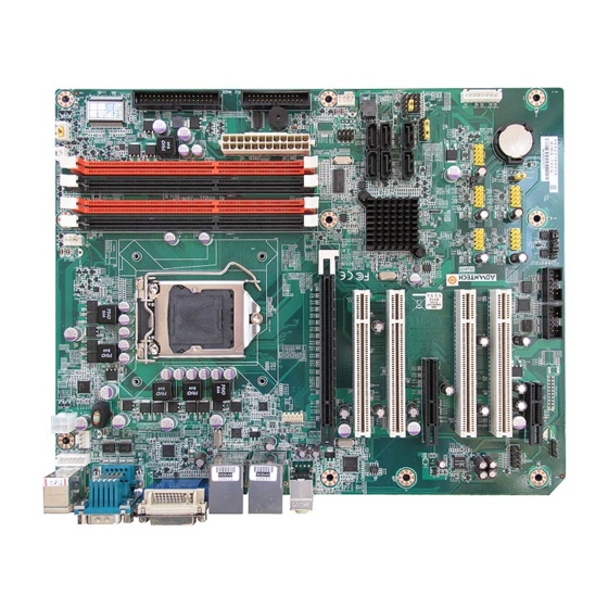
JCASE1 USB56 PSON1 JIR1+JWDT1+ JOBS1 36 9 12 FDD1 25 8 11 EATXPWR1 SPI_CN1 SATA VOLT1 14 7 10 LPT1 SPI_CS_CN1 JFP3 1 2 345 SYSFAN2 JFP1+JFP2 Figure 1.1 Jumper and Connector Locations Figure 1.2 I/O connectors AIMB-780 User Manual... -
Page 19: Aimb-780 Block Diagram
PCI1 ~ 4 Edge Connector 32 bit/33 MHz PCI Bus LPC Bus Audio Codec Super IO Infineon SLB9635 TPM ALC888 BIOS Winbond Fintek 81216AD 1.2 (optional) W83627DHG-P 2 COM, 2 COM PS/2, WDT Figure 1.3 AIMB-780 Block Diagram AIMB-780 User Manual... -
Page 20: Safety Precautions
Caution! There is a danger of a new battery exploding if it is incorrectly installed. Do not attempt to recharge, force open, or heat the battery. Replace the battery only with the same or equivalent type recommended by the man- ufacturer. Discard used batteries according to the manufacturer’s instructions. AIMB-780 User Manual... -
Page 21: Jumper Settings
1.8.2 CMOS clear (JCMOS1) The AIMB-780 motherboard contains a jumper that can erase CMOS data and reset the system BIOS information. Normally this jumper should be set with pins 1-2 closed. If you want to reset the CMOS data, set J1 to 2-3 closed for just a few sec- onds, and then move the jumper back to 1-2 closed. -
Page 22: Watchdog Timer Output (Jwdt1)
1.8.3 Watchdog timer output (JWDT1) The AIMB-780 contains a watchdog timer that will reset the CPU. This feature means the AIMB-780 will recover from a software failure or an EMI problem. The JWDT1 jumper settings control the outcome of what the computer will do in the event the watchdog timer is tripped. -
Page 23: System Memory
1.11 Cache Memory The AIMB-780 supports a CPU with one of the following built-in full speed L2 caches: The built-in second-level cache in the processor yields much higher performance than conventional external cache memories. - Page 24 AIMB-780 User Manual...
-
Page 25: Chapter 2 Connecting Peripherals
Chapter Connecting Peripherals... -
Page 26: Introduction
If you have a number of cards installed, you may need to par- tially remove a card to make all the connections. Floppy Drive Connector (FDD1) You can attach up to two floppy disk drives to the AIMB-780’s onboard controller. You can use 3.5" (720 KB, 1.44 MB) drives. AIMB-780 User Manual... -
Page 27: Parallel Port (Lpt1)
Parallel Port (LPT1) The parallel port is normally used to connect the motherboard to a printer. The AIMB- 780 includes an onboard parallel port, accessed through a 25-pin flat-cable connec- tor, LPT1. AIMB-780 User Manual... -
Page 28: Usb Ports (Lan1_Usb12, Lan2_Usb3/4, Usb5/6, Usb7/8, Usb9/10, Usb11/12 & Usb13/14)
480 Mbps and fuse protection are supported. The USB interface can be disabled in the system BIOS setup. The AIMB-780 is equipped with one or two high-performance 1000 Mbps Ethernet LANs. They are supported by all major network operating systems. The RJ-45 jacks on the rear plate provide convenient 1000Base-T operation. -
Page 29: Vga Connector And Dvi-D Connector (Vga1+Dvi1)
VGA Connector and DVI-D Connector (VGA1+DVI1) The AIMB-780 includes both VGA and DVI-D interface that can drive conventional CRT and LCD displays. Pin assignments of VGA1 and DVI1 are detailed in Appendix AIMB-780 User Manual... -
Page 30: Serial Ports (Com1, Com2, Com3 & Com4)
COM3 COM4 The AIMB-780 offers four serial ports (two on the rear panel and two onboard). JSETCOM3 is used to select the RS 232/422/485 mode for COM3. These ports can connect to a serial mouse, printer or communications network. The IRQ and address ranges for both ports are fixed. -
Page 31: Ps/2 Keyboard And Mouse Connector (Kbms1)
PS/2 Keyboard and Mouse Connector (KBMS1) Two 6-pin mini-DIN connectors (KBMS1) on the rear panel of the motherboard pro- vide PS/2 keyboard and mouse connections. AIMB-780 User Manual... -
Page 32: External Keyboard & Mouse (Kbms2)
External Keyboard & Mouse (KBMS2) There is also an extra onboard external keyboard and mouse connector on the moth- erboard. This gives system integrators greater flexibility in designing their systems. AIMB-780 User Manual... -
Page 33: Cpu Fan Connector (Cpufan1)
CPU Fan Connector (CPUFAN1) If a fan is used, this connector supports cooling fans that draw up to 500 mA (6 W). AIMB-780 User Manual... -
Page 34: System Fan Connector (Sysfan1 And Sysfan2)
2.10 System FAN Connector (SYSFAN1 and SYSFAN2) SYSFAN1 SYSFAN2 If a fan is used, this connector supports cooling fans that draw up to 500 mA (6 W). AIMB-780 User Manual... -
Page 35: Front Panel Connectors (Jfp1, Jfp2 & Jfp3)
2.11 Front Panel Connectors (JFP1, JFP2 & JFP3) There are several external switches and LEDs to monitor and control the AIMB-780. 3 6 9 12 2 5 8 11 1 4 7 10 1 2 34 5 2.11.1 Power LED and Keyboard Lock (JFP3) JFP3 is a 5-pin connector for the power LED. -
Page 36: Hdd Led Connector (Jfp2 Pins 2 & 5)
Many computer cases offer the convenience of a reset button. 2.12 Line Out, Mic In Connector (AUDIO1) Line Out MIC In Line Out can be connected to external audio devices like speakers or headphones. Mic In can be connected to a microphone. AIMB-780 User Manual... -
Page 37: 8-Pin Alarm Board Connector (Volt1)
2.13 8-pin Alarm Board Connector (VOLT1) VOLT1 connects to the alarm board of Advantech chassis. These alarm boards give warnings if a power supply or fan fails; if the chassis overheats; or if the backplane malfunctions. AIMB-780 User Manual... -
Page 38: Case Open Connector (Jcase1)
2.14 Case Open Connector (JCASE1) JCASE1 is for chassis with a case open sensor. The buzzer on the motherboard sounds if the case is opened. AIMB-780 User Manual... -
Page 39: Front Panel Lan Indicator Connector (Lan_Led1)
2.15 Front Panel LAN Indicator Connector (LAN_LED1) Table 2.2: Front Panel LAN Indicator Connector LAN Mode Indicator G-LAN Link ON Green ON G-LAN Active Green Flash G-LAN Link Off Green OFF AIMB-780 User Manual... -
Page 40: Serial Ata Interface (Sata1, Sata2, Sata3, Sata4, Sata5 & Sata6)
2.16 Serial ATA Interface (SATA1, SATA2, SATA3, SATA4, SATA5 & SATA6) AIMB-780 features six high performance serial ATA interface (up to 300 MB/s) which eases cabling to hard drives with thin and long cables. AIMB-780 User Manual... -
Page 41: Pci Slots (Pci 1 ~ Pci 4)
2.17 PCI Slots (PCI 1 ~ PCI 4) The AIMB-780 provides four 32-bit / 33 MHz PCI slots. Note! 64-bit PCI or PCI-X expansion cards installed in the PCI 2 slots will not fit because of the south bridge heat sink. If you want to use 64-bit PCI or PCI-X expansion cards, please install them in the PCI 1, PCI 3 or PCI 4. -
Page 42: Pcie X16 Expansion Slot (Pciex16_1)
2.18 PCIe x16 Expansion Slot (PCIEX16_1) The AIMB-780 provides a PCIe x16 slot for users to install add-on VGA cards when their applications require higher graphics performance than the CPU embedded graphics controller can provide. AIMB-780 User Manual... -
Page 43: Pciex4_1
2.19 PCIEX4_1 AIMB-780 User Manual... -
Page 44: Pciex1_1
2.20 PCIEX1_1 AIMB-780 User Manual... -
Page 45: Auxiliary 4-Pin Power Connector (Atx12V1)
AIMB-780. ATX1 must be used to provide suffi- cient 12 V power to ensure the stable operation of the system. 2.22 SPI Flash connector(SPI_CN1) SPI flash card pin header which can flash BIOS while AIMB-780 can not be power on and ensures platform integrity. AIMB-780 User Manual... - Page 46 AIMB-780 User Manual...
-
Page 47: Bios Operation
Chapter BIOS Operation... -
Page 48: Figure 3.1 Main Setup Screen
The Setup program uses a number of menus for making changes and turning the special features on or off. This chapter describes the basic navigation of the AIMB-780 setup screens. Figure 3.1 Main setup screen AMI’s BIOS ROM has a built-in Setup program that allows users to modify the basic... -
Page 49: Main Menu
Date using the <Arrow> keys. Enter new values through the keyboard. Press the <Tab> key or the <Arrow> keys to move between fields. The date must be entered in MM/DD/YY format. The time must be entered in HH:MM:SS format. AIMB-780 User Manual... -
Page 50: Advanced Bios Features Setup
Advanced BIOS Features Setup Select the Advanced tab from the AIMB-780 setup screen to enter the Advanced BIOS setup screen. You can select any of the items in the left frame of the screen, such as CPU configuration, to go to the sub menu for that item. You can display an Advanced BIOS Setup option by highlighting it using the <Arrow>... -
Page 51: Cpu Configuration
3.3.1 CPU Configuration Figure 3.4 CPU Configuration Setting (1) Figure 3.5 CPU Configuration Setting (2) AIMB-780 User Manual... - Page 52 This function saves CPU power consumption when in system halt state. When enabled, the CPU speed and voltage will be reduced during system halt state to save power consumption. You may choose to enable or disable it. AIMB-780 User Manual...
-
Page 53: Ide Configuration
IDE Detect Time Out (Sec) This item allows you to select the time out value for detecting ATA/ATAPI device(s). ATA(PI) 80 Pin Cable Detection Select the mechanism for detecting 80Pin ATA(PI) Cable. There are three options, [Host & Device]\[Host]\[Device] AIMB-780 User Manual... -
Page 54: Floppy Configuration
Figure 3.7 Floppy Configuration Floppy A This item allows users to select the type of floppy drive connected to the system. Floppy B This item allows users to select the type of floppy drive connected to the system. AIMB-780 User Manual... -
Page 55: Super I/O Configuration
This option configures serial port 3 base IRQ. Serial port3 Mode This option configures serial port 3 mode. Serial Port 4 Address This option configures serial port 4 base address. Serial Port 4 IRQ This option configures serial port 4 base IRQ. AIMB-780 User Manual... -
Page 56: Hardware Health Configuration
The onboard hardware monitor automatically detects and displays the system tem- peratures. CPU Temperature The onboard hardware monitor automatically detects and displays the CPU tempera- tures. CPUFAN Speed Show CPU FAN speed [xxxxRPM]. CPUFAN0 Mode Setting To enable or disable the Smart fan control feature. AIMB-780 User Manual... -
Page 57: Acpi Settings
ACPI Settings Figure 3.10 ACPI Settings AIMB-780 User Manual... -
Page 58: General Acpi Configuration
Sets the ACPI suspend mode to S3/STR (Suspend to RAM) Report Video on S3 Resume (This item would be offered when Suspend mode is set to Auto or S3) Determines whether to invoke VGA BIOS post on S3/STR resume AIMB-780 User Manual... -
Page 59: Chipset Acpi Configuration
3.4.2 Chipset ACPI Configuration Figure 3.12 Chipset ACPI Configuration APIC ACPI SCI IRQ Enable/Disable APIC ACPI SCI IRQ. High Performance Event Timer Enable/Disable High performance event timer. AIMB-780 User Manual... -
Page 60: Ahci Configurtion
AHCI Port1-6 [XXXX] Displays the status of auto-detection of SATA devices. AHCI Port1-6 [Auto] [Auto] Allows automatic selection of the device type connected to the system. [Not Detected] Selects this option if no SATA devices are installed. AIMB-780 User Manual... -
Page 61: Asf Configuration
ASF (Alert Standard Format) provides standards-based alerting and remote control. Both the alerting and remote control capabilities of ASF are hardware-based and local to the networking solution on managed systems. This allows these solutions CPU and OS independence, providing a persistent connection with the management console. AIMB-780 User Manual... -
Page 62: Mps Configuration
This feature is only applicable to multiprocessor motherboards as it specifies the ver- sion of the Multi-Processor Specification (MPS) that the motherboard will use. The MPS is a specification by which PC manufacturers design and build Intel architecture systems with two or more processors. AIMB-780 User Manual... -
Page 63: Remote Access Configuration
The Optimal and Fail-Safe default setting is Disabled. Note! If you want to use SOL, which is provided by Intel AMT, you have to enable the Remote access feature. AIMB-780 User Manual... -
Page 64: Trusted Computing (Optional)
PC, called a Trusted Platform Module (TPM). TPM is a secure key generator and key cache management component, it enables protected storage of encryption keys and authentication credentials for enhanced security capabilities. Figure 3.17 Trusted Computing Configuration AIMB-780 User Manual... -
Page 65: Usb Configuration
Legacy USB1.1 HC Support (This item is offered in QG2 SKU) Allows the system to detect the presence of USB devices at startup. If detected, the USB controller legacy mode is enabled. If no USB device is detected. the legacy USB support is disabled. AIMB-780 User Manual... -
Page 66: Advanced Pci/Pnp Settings
Advanced PCI/PnP Settings Select the PCI/PnP tab from the AIMB-780 setup screen to enter the Plug and Play BIOS Setup screen. You can display a Plug and Play BIOS Setup option by highlight- ing it using the <Arrow> keys. All Plug and Play BIOS Setup options are described in this section. -
Page 67: Boot Settings
Boot Settings Figure 3.20 Boot Setup Utility Figure 3.21 Boot Setting Configuration AIMB-780 User Manual... -
Page 68: Security Setting
Displays “Press DEL to run Setup” in POST. Interrupt 19 Capture Some add-on cards' option ROMs need Interrupt 19, this is to enable or disable sup- porting this kind of add-on cards. Security Setting Figure 3.22 Password Configuration AIMB-780 User Manual... -
Page 69: Advanced Chipset Settings
Select Security Setup from the AIMB-780 Setup main BIOS setup menu. All Security Setup options, such as password protection and virus protection are described in this section. To access the sub menu for the following items, select the item and press <Enter>:... -
Page 70: North Bridge Chipset Configuration
This setting allows the user to select which graphics controller to be the primary graphic device when booting up. IGD Graphics Mode Select Allows you to decide whether to use the integrated GPU and select the amount of memory used by the integrated GPU. AIMB-780 User Manual... -
Page 71: South Bridge Chipset Configuration
Enable or disable Integrated USB 2.0 RMH#1 EHCI Controller#2 Enable or disable Integrated USB 2.0 RMH#2 LAN1 Controller Enables or disables the LAN1 controller. LAN1 Option-ROM Enables or disables LAN1 option-ROM. Resume On LAN1 Enables or disables LAN1 resuming. AIMB-780 User Manual... -
Page 72: Intel Amt Configuration
Restore on AC Loss This allow the user to define how the system responds to power restore after AC power loss. Power Type This allows the user to choose power type. 3.8.3 Intel AMT Configuration Figure 3.26 Intel AMT Configuration AIMB-780 User Manual... -
Page 73: Intel Vt-D Configuration
This item allows the user to set delay times to show "Ctrl + P" for entering ME setting configuration. 3.8.4 Intel VT-d Configuration Figure 3.27 Intel VT-d Configuration Intel VT-d Configuration To support Intel chipset virtualization technology for directed I/O. AIMB-780 User Manual... -
Page 74: Me Subsystem Configuration
This allows the user to enable or disable HECI function of ME. ME-IDER This allows the user to enable or disable IDE redirection function of ME. ME-KT This allows the user to enable or disable KT function of ME. AIMB-780 User Manual... -
Page 75: Ve Subsystem Configuration
VE by using the VE Command Interface (VECI), or via the Intel ME by using the Intel AT-d Host Command Interface (DHCI); which uses HECI. The VE can ensure that access requests outside the PBA ranges are prevented given that PBA code exe- cutes on the host processor. AIMB-780 User Manual... -
Page 76: Exit Option
Select Discard Changes from the Exit menu and press <Enter>. Load Optimal Defaults The AIMB-780 automatically configures all setup items to optimal settings when you select this option. Optimal Defaults are designed for maximum system performance, but may not work best for all computer applications. In particular, do not use the Opti- mal Defaults if your computer is experiencing system configuration problems. - Page 77 Load Failsafe Defaults The AIMB-780 automatically configures all setup options to failsafe settings when you select this option. Failsafe Defaults are designed for maximum system stability, but not maximum performance. Select Failsafe Defaults if your computer is experi- encing system configuration problems.
- Page 78 AIMB-780 User Manual...
-
Page 79: Chapter 4 Chipset Software Installation Utility
Chapter Chipset Software Installation Utility... -
Page 80: Before You Begin
Before you begin To facilitate the installation of the enhanced display drivers and utility software, read the instructions in this chapter carefully. The drivers for the AIMB-780 are located on the software installation CD. Note! The files on the software installation CD are compressed. Do not attempt to install the drivers by copying the files manually. -
Page 81: Windows Xp / Windows 7 Driver Setup
Insert the driver CD into your system's CD-ROM drive. You can see the driver folders items. Move the mouse cursor over the folder "CSI". In CSI folder, you can click "setup.exe" to complete the implement of the driver Click setup to execute program. AIMB-780 User Manual... - Page 82 AIMB-780 User Manual...
-
Page 83: Chapter 5 Vga Setup
Chapter VGA Setup... -
Page 84: Introduction
See Chapter 4 for information on installing the INF driver. Insert the driver CD into your system's CD-ROM drive. You can see the driver folders items. Navigate to the "VGA" folder and click "setup.exe" to complete the installation of the drivers for Windows 7, XP. AIMB-780 User Manual... -
Page 85: Chapter 6 Lan Configuration
Chapter LAN Configuration... -
Page 86: Introduction
Introduction The AIMB-780 has dual Gigabit Ethernet LANs via dedicated PCI Express x1 lanes (Intel 82578DM (LAN1) and 82583V (LAN2)) that offer bandwidth of up to 500 MB/ sec, eliminating the bottleneck of network data flow and incorporating Gigabit Ether- net at 1000 Mbps. -
Page 87: Appendix A Programming The Watchdog Timer
Appendix Programming the Watchdog Timer... -
Page 88: Watchdog Timer Overview
The AIMB-780’s watchdog timer can be used to monitor system software operation and take corrective action if the software fails to function within the programmed period. This section describes the operation of the watchdog timer and how to pro- gram it. - Page 89 Unlock W83627DHG-P Select register of watchdog timer Enable the function of the watchdog timer Use the function of the watchdog timer Lock W83627DHG-P AIMB-780 User Manual...
-
Page 90: Example Programs
Inc dx Mov al,08h Out dx,al ;----------------------------------------------------------- Dec dx; Enable the function of watchdog timer Mov al,30h Out dx,al Inc dx Mov al,01h Out dx,al ;----------------------------------------------------------- Dec dx ; Set second as counting unit Mov al,0f5h Out dx,al AIMB-780 User Manual... - Page 91 Dec dx ; Set minute as counting unit Mov al,0f5h Out dx, al Inc dx In al,dx Or al, 08h Out dx,al ;----------------------------------------------------------- Dec dx ; Set timeout interval as 5 minutes and start counting Mov al,0f6h AIMB-780 User Manual...
- Page 92 Inc dx In al,dx Or al,80h Out dx,al ;----------------------------------------------------------- Dec dx ; lock W8362DHG-P Mov al,0aah Out dx,al Enable watchdog timer to be reset by keyboard ;----------------------------------------------------------- Mov dx,2eh ; unlock W83627DHG-P Mov al,87h Out dx,al Out dx,al AIMB-780 User Manual...
- Page 93 Mov al,07h ; Select registers of watchdog timer Out dx,al Inc dx Mov al,08h Out dx,al ;----------------------------------------------------------- Dec dx ; Enable the function of watchdog timer Mov al,30h Out dx,al Inc dx Mov al,01h Out dx,al ;----------------------------------------------------------- AIMB-780 User Manual...
- Page 94 Dec dx ; Generate a time-out signal Mov al,0f7h Out dx,al ;Write 1 to bit 5 of F7 register Inc dx In al,dx Or al,20h Out dx,al ;----------------------------------------------------------- Dec dx ; lock W83627DHG-P Mov al,0aah Out dx,al AIMB-780 User Manual...
-
Page 95: Appendix B I/O Pin Assignments
Appendix I/O Pin Assignments... -
Page 96: Floppy Drive Connector (Fdd1)
Floppy Drive Connector (FDD1) Table B.1: Floppy drive connector (FDD1) Signal Signal FDHDIN* INDEX* MOTOR 0* DRIVE SELECT 0* DIRECTION* STEP* WRITE DATA* WRITE GATE* TRACK 0* WRITE PROTECT* READ DATA* HEAD SELECT* DISK CHANGE* * low activity AIMB-780 User Manual... -
Page 97: Parallel Port (Lpt1)
Table B.2: Parallel Port (LPT1) Signal Signal STROBE* AUTOFD* ERR* INIT* SLCTINI* ACK* BUSY SLCT USB Header (USB56, USB78, USB910, USB1112 & USB1314) USB56 USB78 USB910 USB1112 USB1314 Table B.3: USB Header (USB56,USB78,USB910,USB1112,USB1314) Signal Signal USB_VCC5 USB_VCC5 USB_D- USB_D- USB_D+ USB_D+ AIMB-780 User Manual... -
Page 98: Vga Connector (Vga1)
VGA Connector (VGA1) Table B.4: VGA Connector (VGA1) Signal Signal GREEN BLUE H-SYNC V-SYNC RS-232 Interface (COM3 & COM4) Table B.5: RS-232 Interface (COM1) Signal AIMB-780 User Manual... -
Page 99: Ps/2 Keyboard And Mouse Connector (Kbms1)
PS/2 Keyboard and Mouse Connector (KBMS1) Table B.6: Keyboard and Mouse Connector (KBMS1) Signal KB DATA KB VCC KB CLK M_DATA M_VCC M_CLK External Keyboard Connector (KBMS2) Table B.7: External Keyboard Connector (KBMS2) Signal KB CLK KB DATA MS DATA MS CLK AIMB-780 User Manual... -
Page 100: Infrared (Ir) Connector (Jir1)
CPU/System Fan Power Connector (SYSFAN1/ SYSFAN2) Table B.9: Fan Power Connector (SYSFAN1/CHAFAN1) Signal +12 V DETECT B.10 Power LED and Keyboard Lock (JFP3) Table B.10: Power LED and Keyboard Lock (JFP3) Function LED power (+5 V) Ground #keylock Ground AIMB-780 User Manual... -
Page 101: External Speaker Connector (Jfp2)
Table B.11: External Speaker Connector (JFP2) Function SPK_VCC SPK_OBS SPK_BUZ SPK_OUT B.12 Reset Connector (JFP1) Table B.12: Reset Connector (JFP1) Signal RESET B.13 HDD LED Connector (JFP2) Table B.13: HDD LED Connector (JFP2) Signal HDD_LED+ HDD_LED- B.14 ATX Soft Power Switch (JFP1) AIMB-780 User Manual... -
Page 102: Table B.14:Atx Soft Power Switch (Jfp1)
Table B.14: ATX Soft Power Switch (JFP1) Signal PWR-BTN B.15 H/W Monitor Alarm (JOBS1) Table B.15: H/W Monitor Alarm (JOBS1) Signal Error Beep OBS Beep alarm B.16 SM Bus Connector (JFP2) Table B.16: SM Bus Connector (JFP2) Signal SMB_DATA SMB_CLK AIMB-780 User Manual... -
Page 103: Usb/Lan Ports (Lan1_Usb12 And Lan2_Usb34)
Table B.17: USB Port Signal Signal VCC_DUAL Data0+ Data0- Table B.18: Giga LAN 10/100/1000 Base-T RJ-45 port Signal Signal MID0+ MID2+ MID0- MID2+ MID1+ MID3+ MID1- MID3+ B.18 Line Out, Mic IN Connector (AUDIO1) Line Out MIC In AIMB-780 User Manual... -
Page 104: Front Panel Audio Connector (Fpaud1)
Front Panel Audio Connector (FPAUD1) Table B.19: Front Panel Audio Connector (FPAUD1) Signal MIC2_L AGND MIC2_R PRESENSE LIN2_R MIC_DEC FIO_JD LIN2_L LINEOUT2_DEC B.20 8-pin Alarm Board Connector (VOLT1) Table B.20: 8-pin Alarm Board Connector (VOLT1) Signal Signal 5VSB VCC3 -12V +12V AIMB-780 User Manual... -
Page 105: Case Open Connector (Jcase1)
Table B.22: LAN LED Connector (LANLED1) Signal Signal LAN1_LINK/ACT LAN2_LINK/ACT 3VDUAL 3VDUAL LAN1_LINK1000 LAN2_LINK1000 LAN1_LINK100 LAN2_LINK100 3VDUAL B.23 SPI_CN1: SPI fresh card pin connector Table B.23: SPI_CN1:SPI fresh card pin connector Signal Signal +3VSB SPI_CS# SPI_CLK SPI_MISO SPI_MOSI AIMB-780 User Manual... -
Page 106: System I/O Ports
3D0-3DF Color/graphics monitor adapter 3F0-3F7 Diskette controller 3F8-3FF Serial port 1 B.25 DMA Channel Assignments Table B.25: DMA channel assignments Channel Function Available Available Floppy disk (8-bit transfer) Available Cascade for DMA controller 1 Available Available Available AIMB-780 User Manual... -
Page 107: Interrupt Assignments
1st MB Memory Map Table B.27: 1st MB memory map Addr. range (Hex) Device E0000h - FFFFFh BIOS CC000h - DFFFFh Unused C0000h - CBFFFh VGA BIOS A0000h - BFFFFh Video Memory 00000h - 9FFFFh Base memory AIMB-780 User Manual... - Page 108 No part of this publication may be reproduced in any form or by any means, electronic, photocopying, recording or otherwise, without prior written permis- sion of the publisher. All brand and product names are trademarks or registered trademarks of their respective companies. © Advantech Co., Ltd. 2010...
Need help?
Do you have a question about the AIMB-780 and is the answer not in the manual?
Questions and answers