
Subscribe to Our Youtube Channel
Related Manuals for DIG LEIT-2ET


Summary of Contents for DIG LEIT-2ET
- Page 1 LEIT-2ET Two Station Weather Based Ambient Light Powered Wireless Irrigation Controller I N S T R U C T I O N M A N U A L...
-
Page 2: Table Of Contents
2.1 Solenoid and valve installation ……………………………………… 11 2.2 Controller installation ……………………………………………… 13 A. Valve box mounting dome ……………………………………… 13 B. Mounting column ……………………………………………… 15 C. Valve mounting ………………………………………………… 17 2.3 Maximum wire run ………………………………………………… 18 3. Initial LEIT-2ET connection ……………………………………………… 18 3.1 Connecting to a LEIT-2ET controller for the first time ………………… 18 4. Using a sensor ………………………………………………………… 20 4.1 Sensor installation ………………………………………………… 20 4.2 Compatible sensors ………………………………………………… 21 5. Troubleshooting ……………………………………………………… 21 5.1 Troubleshooting controller …………………………………………... -
Page 3: Introduction
Introduction Thank you for purchasing DIG’s LEIT-2ET two station, weather based, ambient light (solar) powered, wireless irrigation controller, which operates as part of the LEIT-2ET wireless irrigation system. This manual describes how to get the LEIT-2ET controller up and running. After reading the manual and becoming familiar with the basic functions of the controller, the user can refer to the manual for less common tasks in the future. About the LEIT-2ET System The LEIT-2ET weather based wireless irrigation control system comprises the LEIT-2ET weather based two-station ambient light (solar) powered irrigation controller with a rain sensor connection, the LEIT RC2ET handset, and the LEIT WWS or LEIT WWSE ambient light (solar) powered weather station. Introduction The LEIT-2ET, a two station ambient light (solar) powered wireless irrigation controller, is an advanced and cost effective weather based wireless device that is programmed using the LEIT RC2ET remote control handset. Site information entered into the LEIT RC2ET remote control handset is downloaded into the LEIT-2ET controller, and with hourly weather data received from the LEIT WWS or LEIT WWSE wireless solar powered weather station, the LEIT-2ET controller calculates the daily local microclimate evapotranspiration (ET). The final result is used for a daily adjustment or override of the current scheduled irrigation program. The LEIT-2ET includes a photovoltaic module (PVM panel), 2 pairs of 18” (45 cm) station wires (labeled #V1 and #V2) used to connect the controller with up to two S-305DC solenoids, plus a pair of yellow wires for sensor connection. The LEIT-2ET has an ultra-compact photovoltaic module that harnesses light energy to generate electricity that is stored and used to power the controller day and night in any kind of weather. The programming and operation of the LEIT-2ET controller is conducted using the LEIT RC2ET remote control handset, which has an operating range of up to 350 ft (100 m) line of sight, by way of 2-way radio communication. After installation, no further visits to the controller are required. -
Page 4: Technical Assistance
IMPORTANT: Communication between the LEIT RC2ET remote control handset, the LEIT-2ET controller, and the LEIT WWS or LEIT WWSE weather station is automatically limited to daylight hours when there is sufficient light energy. Longer, brighter days will enable the system to operate over extended parts of the day. -
Page 5: Copyright And Compliance
Copyright and Compliance Copyright 2010 DIG Corporation. All rights reserved. LEIT-2ET and LEIT RC2ET are each trademarks of DIG Corporation. Patent pending. FCC, IC, Canada and CE certified, Australia and HK compliance. To comply with FCC RF exposure compliance requirements, the antenna used for this transmitter is installed to provide a separation distance of at least 8 inches (20 cm) from all persons (not including hands, wrist, feet and ankles) and must not be co-located or operating in conjunction with any other antenna or transmitter. This device is required to comply with FCC RF exposure requirements for mobile and fixed transmitting devices. This model transceiver generates and uses radio frequency energy. If not installed and used in accordance with the manufacturer’s instructions, it may cause interference to radio and television reception. CONTROLLER FCC ID: UJV-LEIT01 IC: 6694A-LEIT01 HANDSET FCC ID: UJV-LEIT02 IC: 6694A-LEIT02 WEATHER STATION FCC ID: UJV-LEIT03 IC: 6694A-LEIT03 This equipment has been tested and found to comply with the limits for a Class B digital device, pursuant to part 15 of the FCC Rules. These limits are designed to provide reasonable protection against harmful interference in a residential installation. This equipment generates, uses and can radiate radio frequency energy. If not installed and used in accordance with the instructions, the remote may cause harmful interference to radio communications. However, there is no guarantee that interference will not occur in a particular installation. If this equipment does cause harmful interference to radio or television reception, which can be determined by turning the equipment off and on, the user is encouraged to try to correct the interference by one or more of the following measures: • Reorient or relocate the receiving antenna. -
Page 6: Features
Features • Environmentally friendly; certified lead free; uses light (solar) as a source of energy • Power is provided by an efficient photovoltaic module (PVM) and microelectronic management system fueled by ambient light (solar) • Operates up to two (2) stations and a sensor without AC power hookup, batteries, or conventional solar panels • Two (2) independent programs with four (4) start times per program • Used with Unimax S-305DC solenoids, which mount on most brand name valves using one (1) of seven (7) valve adapters • Client ID enables the user to assign a unique identity code to the controller and handset; this is a security feature, which locks out unauthorized users • The LEIT-2ET controller uses information transmitted from the weather station sensors and the LEIT RC2ET handset to override or adjust the daily scheduled irrigation program by adjusting the valve time duration in percents to compensate for evapotranspiration (ET) • The LEIT-2ET can monitor and receive signals from one (1) to five (5) weather stations every hour and uses the daily average data for evapotranspiration (ET) calculation • The LEIT-2ET controller can monitor the weather stations and when ET is set to active will alert the user via the handset if information has not been received or how often the controller has received ET information that day along with the last time information was received • The LEIT-2ET controller can receive information from the weather station(s) to completely stop irrigation if it is raining, freezing or too windy. This information is provided daily, every hour, during daylight hours only • Environmentally friendly, utilizes RoHS compliant components • The LEIT-2ET controller utilizes radio frequency in the ISM band 902-928... - Page 7 • The LEIT-2ET controller communicates with LEIT RC2ET handset and LEIT WWS or LEIT WWSE weather station at a distance of up to 350 feet (100 m) line of site by way of radio communication • The LEIT-2ET controller functions both day and night in any weather and in most outdoor locations • Default program: five (5) minutes per day with a start time of 9 AM on valve one (1) with no previous programming, if ID has been assigned • Non-volatile memory retains program and controller integrity (excluding time) • Program stacking feature prevents hydraulic overload • Custom grouping of the two (2) stations allows the controller to operate the two (2) valves at the same time if hydraulic limitations are not exceeded • Available with 18” (45 cm) color-coded 16 gauge wires for each valve and rain sensor • Built from tough, rugged material and is resistant to harsh environmental conditions • Completely waterproof, complies with IP68 requirements • The LEIT-2ET has three (3) mounting configurations including green, tan and purple valve box mounts, direct-to-valve clip mounting and column mounting with 25” (63 cm) or 50“ (127 cm) mounting columns • Three-year manufacturer’s warranty Electrical Specifications: • Controller power requirements for normal operation: Minimum of 3,000 LUX • Controller input: 3,000-100,000+ LUX • Controller output: 9-volt DC pulse • Controller station capacity: One 6-9 volt DC pulse, two-way magnetic...
-
Page 8: System
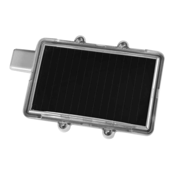
1. System 1.1 Parts Identification 1. P VM (photovoltaic module) harnesses the energy of light and generates the electricity to power the unit day and night in any weather 2. Antenna 3. Stations and sensor wires 1.2 System Components To properly install the LEIT-2ET controller, the following components are needed: 1. Control unit: LEIT-2ET two station weather based ambient light (solar) powered wireless controller. 2. T he controller is installed using one (1) of the mounting configurations available: a. Model 30-830: Valve box mounting dome, color green b. Model 30-835: Valve box mounting dome, color tan c. Model 30-836: Valve box mounting dome, color purple d. Model 30-831*: Mounting column plastic attachment used with galvanized mounting column; i. MCOL2S: 25” (63 cm) galvanized mounting column ii. MCOL2L: 50” (123 cm) galvanized mounting... - Page 9 Additional system components e. Model 30-832: Valve clip attachment with four (4) screws *The mounting column includes a mounting tool kit with cement glue to firmly attach the mounting bracket to the column. 3. 3 05DC-XXX complete in-line valve with solenoid or S-305DC solenoid (one (1) for each valve used). 4. Seven (7) solenoid adapters are available to fit most valves: a. M odel 30-920 use with BERMAD series 200, HIT series 500, DOROT series 80, GRISWOLD series 2000, DW and BUCKNER series VB valves b. M odel 30-921 use with RAIN BIRD DV, DVF, PGA, PEB (1” only), GB, EFB- CP, BPE, PESB (1” only) and ASVF valves c. Model 30-922 use with HUNTER series ASV, HPV, ICV, PGV, SRV, IBV and ASVF valves d. Model 30-923 use with WEATHERMATIC series 12000, 21000, 8200CR valves e. M odel 30-924 use with IRRITROL series 100, 200B, 205, 217B, 700, 2400, 2500, 2600 and TORO series 220, P220 valves f. Model 30-925 use with SUPERIOR series 950, HUNTER HBV and TORO series 252 valves (1.5” and larger) g. Model 30-926 use with RAIN BIRD series PEB and PESB (1 1/2” and 2”only) valves A1 O-ring B1 O-ring C1 O-ring D1 O-ring...
-
Page 10: Tools And Supply Requirements
1. Standard wire stripper. 2. P hillips screwdriver (#1) if using the valve clip attachment or the mounting column plastic attachment, or Phillips screwdriver (#2) if using the valve box mounting dome. 3. C oncrete: approximately one (1) 90 lb (40 kg) bag, if using the mounting column installation. 4. WATERPROOF WIRE CONNECTORS (not included). 1.4 Quick Installation Setup and Operation Review In order to establish communication for the first time between a LEIT RC2ET handset and LEIT-2ET two station weather based, ambient light (solar) powered wireless irrigation controller and the LEIT WWS or LEIT WWSE weather station, the following steps must be taken: 1. Charge the LEIT RC2ET handset (see LEIT RC2ET instructions). 2. Set up the LEIT RC2ET handset (see LEIT RC2ET instructions). 3. I nstall the LEIT-2ET controller following the LEIT-2ET installation instructions, see Section 2, then set it out in the light for initial charge. 4. Install the LEIT WWS (with wind sensor) or LEIT WWSE (without wind sensor) weather station following the installation instructions inside each box and allow the controller and weather station to harness light energy. After the weather station has been installed, no wire connection or programming is required for the unit’s operation. -
Page 11: Installation
5. Follow instructions on page 18, 19 and 20, on how to establish initial communication between a LEIT-2ET controller and LEIT RC2ET remote control handset. Installation NOTE: Install the LEIT WWS and/or LEIT WWSE at a minimum of 25 ft (8 m) from the nearest LEIT-2ET controller. 2.1 Solenoid and Valve Installation NOTE: Maximum operating pressure is up to 150 PSI (10.5 BAR). Use DIG’s 305DC-XXX valve or Model S-305DC solenoid and select the appropriate conversion adapter for the valve(s) that will be used with the S-305DC solenoid (see list on page 9, #4). 1. Shut off the main line to the valve. 2. I nstall the valve (model 305DC-XXX) or unscrew the conventional solenoid from the valve installed and remove the solenoid housing, solenoid stem, plunger, spring, and O-ring (if necessary). - Page 12 5. Screw model S-305DC solenoid into the selected adapter. Tighten the solenoid by hand, but do not over tighten (see B). m components 6. A fter installation is complete, turn the water supply on and pressurize the main line. The valves will open momentarily and then shut off. Test each valve in manual operation by turning the solenoid to the left a half turn or until the valve opens (see C). 7. S plice the solenoid hot wires (red) to the controller incoming station wire (V1 red). Splice the solenoid white wire to the single incoming white wire (V1). If needed, repeat for the second valve. USE 2 CONVENTIONAl DRy- SPlICE WATERPROOF CONNECTORS. Leave slack on each side of the wires so that repairs can be carried out easily. NOTE: The solenoid operates only with 2-way normally closed valves. NOTE: V1 may be identified by label or striped wires.
-
Page 13: Controller Installation
IMPORTANT: If a valve remains open in manual operation, you may need to examine the solenoid adapter and sleeve to see that they are installed correctly and the adapter is firmly secured. Do not over tighten the solenoid to the valve and do not cross thread the adapter into the solenoid cavity. CAUTION: For all valves with built-in internal manual bleed lever, make sure the lever is in closed position. - Page 14 2. I nsert the controller into the mounting dome (see ). 3. I nsert the controller wires into the valve box cover (see ). 4. U se #2 Phillips screwdriver to attach the mounting dome to the valve box cover with the #10 Phillips head screws that are included with the mounting dome (see ). 5. T here are 6 wires (or three sets) from the controller, one (1) pair for each valve and one (1) pair for sensor connection (labeled V-1, V-2 and S on the housing where the wires enter the controller). Connect the controller’s output station wire (V1 red) to the hot wires (red) on the solenoid. Then connect the controller’s output station common wire (V1 white) to the white wire on the solenoid USINg CONVENTIONAl DRy-SPlICE WATERPROOF CONNECTORS. Repeat the same steps for station 2. Leave slack in the wires on each side so repairs can be carried out easily (see ). NOTE: V1 may be identified by label or striped wires.
-
Page 15: Mounting Column
6. R eattach the valve box cover on top of the valve box and, if available, lock the cover to the box (recommended) (see ). Option B: Mounting Column (model 30-831) 1. E xcavate a trench from the valve to the column location and then pull a set of colored wires from the valve area to the mounting column location (one (1) pair for each valve). Each pair should consist of one (1) white wire, and one (1) red or colored wire, preferably of differing colors. Each pair should be taped and marked separately at both ends, so that the wires do not get cross-connected (see ). 2. I nsert the pairs of wires through the bottom of the mounting column and push the wires up through the column until at least 6” (15 cm) of wire extends from the top of the mounting column (see ). 3. I nstall the mounting column, setting the curved bottom of the mounting column in an 8” x 8” x 6” (20 x 20 x 15 cm) frame and pour in the 90 lb (40 kg) sack of cement (see detailed illustration). Make sure the column is vertical Column mounting (phase 1) and the opening in the curved bottom is accessible and unclogged (see ). Column mounting (phase 2) IMPORTANT: Make sure the cement pad is dry before continuing installation. - Page 16 4. P ull the two (2) pairs of field wires from the valves through the center hole in the bottom of the mounting plastic bracket (see ). There are three (3) sets of wires from the controller, one (1) pair for each valve and one (1) pair for sensor connection (labeled V-1, V-2 and S on the housing where the wires enter the controller). First, trim the controller’s valve wires to about 3-4” (7-10 cm) from the controller and then connect the controller output station wire (V1 red and white) to the incoming wires (#1 red or colored and white) using two (2) small WATERPROOF WIRE NUT CONNECTORS. If necessary, repeat the same procedure for valve #2 using the wires labeled V2 (see ). Next, bring the two Column mounting (phase 1) (2) yellow (or yellow and black) sensor wires through the small hole on the side of the mounting bracket (see ). Finally, place the wires with nuts inside the bracket body and secure the plastic bracket into the controller using the four (4) small Phillips screws provided (see - ). 5. N ext, apply a thin layer of cement glue (included with the column) to the top on the outside area of the column and slide the controller mounting bracket into place on top of the column (see ). 6. A t the valves, connect the incoming station wire (V1 red) to the hot wires (red) on the solenoid USINg CONVENTIONAl DRy-SPlICE WATERPROOF CONNECTORS. Connect the controller incoming station common wire (V1 white) to the white wire on the solenoid USINg...
-
Page 17: Valve Mounting
Column mounting (phase 2) Option C: Valve Clip Attachment Bracket (model 30-832) 1. S lide the wires from the controller into the valve clip attachment bracket and connect the valve clip attachment bracket to the controller using the four (4) screws included (see ). 2. C onnect the incoming station wire (V1 red) to the hot wires (red) on the solenoid USINg CONVENTIONAl DRy-SPlICE WATERPROOF CONNECTORS. Connect the controller incoming station common wire (V1 white) to the white wire on the solenoid USINg CONVENTIONAl DRy-SPlICE WATERPROOF CONNECTORS and, if needed, repeat for the second valve and sensor. Leave slack on each side of the wires so that repairs, if needed, can be made easily (see ). -
Page 18: Maximum Wire Run
NOTE: V1 on the bottom of the housing where the wires enter the controller. 3. Attach the controller into place on the top of the solenoid (see ). 2.3 Maximum Wire Run 100’ (30 m) using 18 AWG (0.75 mm) solid core direct burial irrigation wire 200’ (60 m) using 14 AWG (2.5 mm) solid core direct burial irrigation wire 300’ (90 m) using 12 AWG (4 mm) solid core direct burial irrigation wire I nitial LEIT-2ET Connection 3.1 Connecting to a lEIT-2ET controller for the first time NOTE: Prior to initial LEIT-2ET connection, LEIT RC2ET handset Client ID must be set at AAA (factory default setting). In order to begin communication with a new LEIT-2ET controller using the handset, a series of initial setup steps must be made. First, the user connects to the LEIT- 2ET controller via CONTROL ID 00 DEFAULT SETUP. Next, the user must assign the controller a new Control ID (recommended ID # 2-99). At this stage, the user can also change the existing Client ID of the controller (controller default Client ID is AAA) as long as it is also changed on the handset after exiting the controller program. In addition a descriptive controller address or name can be assigned to the controller with up to 14 characters to uniquely identify the location of each LEIT-2ET controller on the system. Step 1: Make sure the LEIT-2ET controller is out in bright light to harness light energy used to power the controller. It will take about 30 minutes, or less, in direct sunlight. Step 2: Splice the two (2) yellow (or yellow and black) sensor wires together using waterproof connectors. This splice will indicate that the controller is ready to... - Page 19 CONNECTED appears momentarily, then, CONTROL ID: 00, NO DESCRIPTION appears. Press again and CONTROL ID: 01, NO DESCRIPTION appears with Ø blinking. At this point the user can assign a new controller ID. b. To assign a controller ID, press or and enter a number (1-9) for the first digit. Press and repeat the steps with the second digit (we recommend changing the ID number to a number higher then 01). Next, assign description, name or address (recommended). The default is NO DESCRIPTION. Press and the first letter of NO DESCRIPTION is blinking. Press or and enter a letter for the first digit. Press and repeat the steps for each letter. After completion, press to download the new information with the new ID number and address. Use the new ID number to connect to this controller and use the address or name to identify the controller location. c. Setting a new client ID (A-Z): The default ID is AAA (this is a security feature). If the controller CLIENT ID is changed from AAA to other letters, the user must update the handset to the same client ID after exiting the controller program. Repeat the steps to select a new ID. When finished, press to connect and upload the new information. ARE YOU SURE? screen appears. Press again to download the information. UPDATE SUCCESSFUL message will appear momentarily confirming that the controller received the information and Setup is updated and complete. After the update is completed the SETUP MENU appears. Exit SETUP MENU and the controller is ready to program. The user can now easily connect back to this controller using the newly assigned CONTROL ID and CLIENT ID. Repeat the steps to program additional controllers. NOTE: When connecting to a LEIT-2 controller, the controller and handset CLIENT ID must be the same. ATTENTION: The two yellow (or yellow and black) sensor wires are left connected so the RAIN OFF alert will not appear. If a rain sensor needs to be added, see Section 4 – Using a Sensor.
-
Page 20: Using A Sensor
CLIENT ID: XXX HW: 1.8 SW:3.2 CONNECT CONNECTED TO CONNECT CONT. SETUP YES / NO 10:00 10:00 10:00 DOWNLOADING UPDATE SUCCESSFUL CONNECT CONNECT CONTROLLER MENU Using a Sensor NOTE: Do not install a sensor until the controller has been given an ID # by the LEIT RC2ET remote control handset. 4.1 Sensor Installation Remove the WATERPROOF CONNECTORS from the LEIT-2ET controller’s yellow (or yellow and black) wires and splice them. Splice the sensor’s two, normally closed (N/C), black wires. Connect one of each yellow wire or one of the yellow and black wires from the controller with one of each black wires from the sensor using WATERPROOF CONNECTORS (if sensor is connected, the sensor will override the program when triggered). -
Page 21: Compatible Sensors
4.2 Compatible Sensors Sensors compatible with LEIT-2ET controllers: Rain sensor: … HUNTER MINI-CLICK II (model 502) and the RAIN BIRD RSD Moisture sensor: ……………………… IRROMETER RA and TGA series Freeze sensor: ………………………………… HUNTER FREEZE-CLICK Troubleshooting The LEIT-2ET weather based wireless irrigation control system is comprised of the LEIT-2ET two station ambient light (solar) powered wireless irrigation controller with a rain sensor connection, the LEIT RC2ET remote control handset, and the LEIT WWS or LEIT WWSE ambient light (solar) powered weather station. The LEIT-2ET weather based wireless irrigation control system is a series of components consisting of the LEIT-2ET two station weather based ambient light (solar) powered wireless irrigation controller, the LEIT RC2ET remote control handset, the LEIT WWS or LEIT WWSE weather station, the S-305DC solenoid, with or without a hydraulic control valve, solenoid adapter and three (3) mounting configurations. It is best to troubleshoot this DC system (like an AC system) by a process of elimination with the goal being to determine which component(s) has failed. The following facts and tips may be helpful to eliminate certain components and facilitate faster troubleshooting. It is assumed that these are installed controllers that are receiving the proper amount of light. Keep in mind that the problem may be with more than one component. -
Page 22: Troubleshooting Controller
1. T o test the controller’s output, connect a solenoid to one of the controller’s red and white wire pairs. Institute a test run via the handset with one (1) minute on the station in question and zero (0) minutes on the other station. If the solenoid is not installed, verify that the plunger retracts and extends or that you hear the sound of the plunger latching. If the solenoid is installed onto a valve, see that the valve turns on and the sprinklers or drip system is working. If it does not turn on, the plunger does not retract and extend, or no sound is heard of the plunger latching, repeat the process using a second solenoid. If the problem continues you may have an issue with the controller wires and the WATERPROOF CONNECTORS. 2. T he LEIT-2ET controllers function only with S-305DC solenoids or 305DC-XXX valves. 3. T he LEIT-2ET controllers function only with compatible sensors (HUNTER MINI-CLICK or RAIN BIRD RSD). 5.2 Troubleshooting Solenoids 1. V erify that the correct solenoid and adapters are being used for the valve in question. 2. V erify that the white and red wires from the solenoid are connected to the white and red wire pair on the controller and that these splices are tight and corrosion free. 3. V erify that no water is leaking externally near the adapter, stem, or bonnet. -
Page 23: Troubleshooting Hydraulic Valve
b. I f the solenoid does not function with a 9-volt battery, check the battery. If the problem with the solenoid continues after using a second battery, it should be replaced. 5. I f the valve is weeping or not closing completely, the adapter being used with the S-305DC solenoid may be loose, cross-threaded, or missing an O-ring, the adapter sleeve could be damaged, or the valve diaphragm inside the valve could be in need of cleaning or replacement. 6. I f the valve is not opening completely, the adapter being used with the S-305DC solenoid may be too Spring 30-906 tight, the adapter sleeve could be damaged, or the valve water passage down stream may be plugged Plunger Assembly and in need of cleaning. 30-905 7. Solenoid parts list (see A). Retainer 30-907 5.3 Troubleshooting Hydraulic Valves 1. V erify that the valve opens and closes. If it does not, the problem is with the valve. a. V erify that the static mainline pressure at the valve is below 150 PSI (10.5 BAR) and above 10 PSI (.7 BAR). -
Page 24: Troubleshooting Control Valve
5.4 Troubleshooting Control Valves 1. Verify that the white common wire is connected to the white common wire on the controller and that the wire is from the same pair. 2. V erify that common and hot wire splices at the valves or splice boxes are tight and made with WATERPROOF CONNECTORS. 3. 1 2 and 14 AWG direct burial single strand solid core irrigation wires are recommended; do not use multi-strand wires. 4. The controller software can detect wire faults or wire shorts on each valve. To review, select the REPORTS icon, then in the REPORTS MENU screen select the CURRENT STATUS icon to review. -
Page 25: Record Chart
RECORD CHART Customer ID Controller ID Handset ID Location / Address Keep this information in a safe place for your records. -
Page 26: Programming Quick Reference Chart
PROgRAMMINg QUICK REFERENCE CHART... -
Page 27: Environment Quick Reference Chart
ET/ENVIRONMENT QUICK REFERENCE CHART... -
Page 28: Warranty
REPLACEMENT OF DEFECTIVE PRODUCTS. SOME STATES DO NOT ALLOW THE EXCLUSION OR LIMITATION OF INCIDENTAL OR CONSEQUENTIAL DAMAGES, SO THE ABOVE LIMITATION OR EXCLUSION MAY NOT APPLY TO YOU. Unattended use for prolonged periods without inspection to verify proper operation is beyond the intended use of this product, and any damage resulting from such use shall not be the responsibility of DIG CORPORATION. There are no warranties which extend beyond the description on the face hereof. In the case of purchase of the product for use other than, for irrigation purposes, DIG CORPORATION hereby disclaims any implied warranties including any warranties of merchantability and fitness for a particular purpose. In the case of the purchase of the product for personal, family or household purposes, DIG CORPORATION disclaims any such warranties to the extent permitted by law. To the extent that any such disclaimer or implied warranties shall be ineffectual, then any implied warranties shall be limited in duration to a period of three years from the date of the original purchase for use by the purchaser. Some states do not allow limitation on how long an implied warranty lasts, so the above limitation may not apply to you. In order to obtain performance under this warranty, the unit must be returned to the factory, along with proof of purchase indicating original date of purchase, shipping prepaid, addressed as follows: DIG CORPORATION, 1210 Activity Drive, Vista, CA 92081-8510. Repaired or replaced units will be shipped prepaid to the name and address supplied with the unit returned under warranty. Allow four weeks for repairs and shipping time. Repair of damaged units not otherwise within warranty may be refused or done at a reasonable cost or charge at the option of DIG CORPORATION. This warranty gives you specific legal rights, and you may also have other rights which vary from state to state. www.digcorp.com e-mail: dig@digcorp.com 1210 Activity Drive 26-070 REVA 022514 DIGCORP Vista, CA 92081-8810, USA Printed in the USA...
Need help?
Do you have a question about the LEIT-2ET and is the answer not in the manual?
Questions and answers