Table of Contents
Advertisement
Quick Links
GM 170 OPERA
MANU
MANU
MANU AL
MANU
MANU
Revision #5
Starting Serial #210262
H&S MANUFACTURING CO.,INC.
P.O. BOX 768 (715) 387-3414 FAX (715) 384-5463
OPERA
OPERA
AL
AL
AND P
AND P
AL AND P
AND P AR
AL
AND P
WARNING
Manufactured By
MARSHFIELD, WISCONSIN 54449
OPERA T T T T T OR'S
OPERA
AR
AR
AR TS LIST
AR
READ AND UNDERSTAND THIS MANUAL
BEFORE OPERATING THIS EQUIPMENT.
UNSAFE OPERATION OR MAINTENANCE OF
THIS EQUIPMENT CAN RESULT IN SERIOUS
INJURY OR DEATH.
OR'S
OR'S
OR'S
OR'S
TS LIST
TS LIST
TS LIST
TS LIST
HSMFG0912
Advertisement
Table of Contents

Related Manuals for H&S GM 170


Summary of Contents for H&S GM 170
- Page 1 GM 170 OPERA OPERA OPERA T T T T T OR’S OPERA OR’S OR’S OR’S OPERA OR’S MANU MANU AND P AND P TS LIST TS LIST MANU AL AL AND P AND P AR AR TS LIST TS LIST...
-
Page 2: Table Of Contents
CONTENTS Warranty & Warranty Registration Card ..........1-2 Manufacturers Statement . -
Page 3: Warranty & Warranty Registration Card
WARRANTY H&S WARRANTY H&S Manufacturing Co., Inc. (“H&S”) warrants this product to be free from defect in material and workmanship. Except as noted below, this warranty term is twelve (12) months from the date of delivery of the product to the original purchaser by an authorized H&S dealer. -
Page 4: Manufacturers Statement
MANUFACTURER’S STATEMENT Your new H&S Grinder-Mixer has been manufactured of the finest quality materials and components. The performance you get from your machine is largely dependent upon how well you read and understand this manual and apply this knowledge. There is a right and a wrong way to do everything. Please do not assume that you know how to operate and maintain your Grinder-Mixer before reading this manual carefully. -
Page 5: Dealer Pre-Delivery Checklist
DEALER PRE-DELIVERY CHECK LIST AFTER COMPLETION, DEALER SHOULD REMOVE AND RETAIN FOR RECORDS After the 170 Grinder-Mixer has been completely set-up, check to be certain it is in correct operating order before delivering to the customer. The following is a list of points to inspect. Check off each item as you have made the proper adjustments and found the item operating satisfactorily. - Page 6 Intentionally Left Blank...
-
Page 7: Dealer Delivery Checklist
DEALER DELIVERY CHECK LIST AFTER COMPLETION, DEALER SHOULD REMOVE AND RETAIN FOR RECORDS This check list that follows is an important reminder of valuable information that should be passed on to the customer at the time this Rake is delivered. Check off each item as you explain it to the customer. - Page 8 Intentionally Left Blank...
-
Page 9: Be Alert Symbol
SAFETY INFORMATION YOUR SAFETY ALERT! IS INVOLVED. THIS SYMBOL IS USED THROUGHOUT THIS BOOK WHENEVER YOUR PERSONAL SAFETY IS INVOLVED. TAKE TIME TO BE CAREFUL. REMEMBER: THE CAREFUL OPERATOR IS THE BEST OPERATOR. MOST ACCIDENTS ARE CAUSED BY HUMAN ERROR. CERTAIN PRECAUTIONS MUST BE OBSERVED TO PREVENT THE POSSIBILITY OF INJURY OR DAMAGE. -
Page 10: Explanation Of Safety Signs
SAFETY INFORMATION Keep signs in good condition. Immediately replace any missing or damaged signs. RECOGNIZE SAFETY INFORMATION This is the safety-alert symbol. When you see this symbol on your machine or in this manual, be alert to the potential for personal injury. Follow recommended precautions and safe operating practices. -
Page 11: Safety Decals
SAFETY INFORMATION... - Page 12 SAFETY INFORMATION -10-...
- Page 13 SAFETY INFORMATION -11-...
-
Page 14: Warning - Owner Must Read And Understand
TRACTORS: This operators manual uses the term “Tractor” when identifying the the power source. W A R N I N G TO PREVENT SERIOUS INJURY OR DEATH BEFORE YOU ATTEMPT TO OPERATE THIS EQUIPMENT, READ AND STUDY THE FOLLOWING INFORMATION. IN ADDITION, MAKE SURE THAT EVERY INDIVIDUAL WHO OPERATES OR WORKS WITH THIS EQUIPMENT, WHETHER FAMILY MEMBER OR EMPLOYEE, IS FAMILIAR WITH THESE SAFETY PRECAUTIONS. -
Page 15: Bolt Torque Chart
-13-... -
Page 16: Set-Up & Assembly
As necessary, drain the water before using the mixer. NOTE: After water has been drained from the mixer, it is advisable to run the GM 170 while empty for a period of time in an attempt to dry the mixer before grinding to eliminate any sticking of material and possible plugging. -
Page 17: Transporting
TRANSPORTING SMV BRACKET & REFLECTORS The grinder-mixer is equipped with a SMV bracket. Red reflector strips are located on the rear of each side of the tank and on the SIA (if applicable). TRANSPORT LIGHTING An optional highway transport lighting kit is available. -
Page 18: Preparing For Operation
4. Maintain a distance of 6”- 12” between the top of the tractor drawbar and the center of the tractor PTO. An 8” distance is standard. Hydraulics The GM 170 requires a 4 hose hook-up; 2 hoses for the discharge auger lift, and 2 hoses for the discharge auger rotation. PREPARING MIXER * Properly lubricate the grinder-mixer, checking the transmission and cyclonic reservoir oil levels, and filling if necessary before operating the grinder-mixer. -
Page 19: Operation
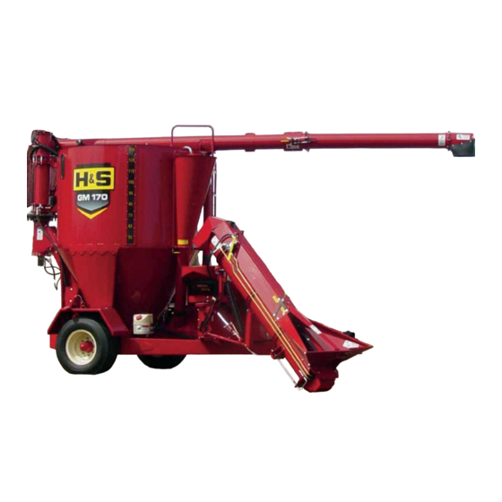
OPERATION EMERGENCY SHUTDOWN In an emergency or in case a foreign object enters the mill inlet, stop mixer operation immediately by disengaging the tractor PTO. GENERAL INFORMATION Check entire unit carefully before first operation. Tighten bolts and set screws that might have come loose in shipping. - Page 20 OPERATION CAPACITY The GM 170 mixing tank capacity is 170 cubic feet or 135 bushels by volume. The tank will hold approximately 6000 lbs of ground feed consisting of average weight corn, small grain and/or concentrates. More or less weight (per tank) is possible, depending upon whether the material that is being ground is lighter or heavier than average.
- Page 21 Hydraulic Pump/Motor Drive The GM 170 has a double sheave on the end of the main drive shaft which is connected by a double banded belt to the hydraulic pump. The pump is belt driven directly off the main drive shaft which is coupled by the telescoping drive to the tractor PTO shaft.
- Page 22 OPERATION Discharge Auger System Ground feed from the mixing tank is discharged by an auger system consisting of three hydraulically motor driven augers that are connected in series so that all augers are synchronized as well as started and stopped together. If any motor malfunctions, the movement of material through the augers will stop immediately.
- Page 23 OPERATION HYDRAULIC OPERATED ATTACHMENTS Swinging Intake Auger (SIA) An optional hydraulic drive Swinging Intake Auger (SIA) attachment conveys material into the mill. The intake auger can be swung in and locked against the mixer tank support brace for transporting, or swung out and locked at any point.
- Page 24 The GM 170 can be fitted with numerous screens that are available with various size holes to accommodate different material and grinding requirements.
- Page 25 OPERATION OVERLOAD PROTECTION Main Drive The GM 170 is furnished with a 5/16 x 1” Grade 5 shear bolt protecting the transfer auger drive shaft, transmission and mixing auger. When the shear bolt fails, the transfer auger and mixing auger will stop turning. Check the rear chain tightener for proper tension if this bolt shears.
- Page 26 OPERATION BLOWER INLET & OUTLET NOTE:The collector cover must always be open while grinding. Plugging in the blower inlet or outlet can be seen by the abnormal amount of dust particles in the air around the top of the collector, and/or the visible presence of dust in the mill throat area and/or a reduced air discharge at the top of the collector.
- Page 27 OPERATION MILL/BLOWER DRIVE BELT SLIPPAGE Overload protection for the mill and blower components is provided by an 8 “A” section drive belt, which connects the mill/blower driven sheave to the drive sheave. The mill and blower will gradually slow down without much reduction in tractor PTO speed if plugging develops from mill/blower drive belt slippage, and stop turning the mill/blower drive shaft if plugging or breakdown occurs in the mill or blower areas.
-
Page 28: Adjustments
ADJUSTMENTS MILL/BLOWER DRIVE The combination mill/blower driven sheave is connected from the main drive sheave by an 8" “A” section banded drive belt. Adjusting bolts are provided to align the drive sheave with the driven sheave as well as to adjust the drive belt tension. Sheave Alignment To align the combination mill/blower driven sheave with the drive sheave, proceed as follows:... - Page 29 ADJUSTMENTS FRONT DRIVE CHAIN The transfer auger/transmission shaft is driven by a sprocket which is connected by the front drive chain to a sprocket on the main drive shaft. The front chain tension is self-adjusted by a spring-loaded idler and does not require adjustment. The chain should be inspected periodically for signs of wear.
- Page 30 ADJUSTMENTS MILL SCREEN COVER LATCHES Over-center handle latches are used to secure the mill cover tightly closed while the mill is being operated. Lock nuts on the bolts of the latches are used to adjust latching tension. This tension should be adjusted and maintained so that some force has to be applied on the handles to lock and unlock them.
-
Page 31: Service
SERVICE HYDRAULIC SYSTEM Hydraulic Pump Sheave Alignment The hydraulic pump drive and driven sheaves must be maintained in correct alignment and be tightly secured at all times. Hydraulic Pump Belt Tension Overload protection for the hydraulic pump is provided by a self-adjusting spring tightener that requires no adjustment. - Page 32 SERVICE MAIN DRIVE SHAFT BEARINGS Main drive shaft bearings are greased by 2 of the remote zerks in grease bank under the step by the mill cover. For bearing replacement, follow steps 1-5 from the previous Belt Replacement section in this chapter.
- Page 33 SERVICE MILL HAMMER ROTATION OR REPLACEMENT To maintain maximum grinding efficiency, the mill hammers should be rotated before wear radius measures ¼” (6 mm). Mill hammers are designed to be conveniently removed and rotated through 4 positions, before they require replacement. The hammers should be replaced when all four corners are worn to ¼”...
- Page 34 SERVICE MIXING AUGER & TUBE The mixing auger should be centered inside the tube at all times. Adjustment bolts are provided on the 4 supports which hold the tube for aligning and centering it around the auger. Access to the adjustment bolts and removing the mixing auger is gained through the tank lid opening in the top of the tank.
- Page 35 SERVICE TRANSMISSION The GM 170 transmission can be removed from the mixer for taking it to the dealer for internal component service. Note: Internal component repairs and replacement should only be attempted by (or under the direction of) an authorized H&S Manufacturing Dealer.
-
Page 36: Optional Features & Accessories
OPTIONAL FEATURES & ACCESSORIES UNLOADING AUGER EXTENSIONS 3’ Folding Auger Extension The 3’ folding discharge auger extension kit consists of a 3’ length of auger which is attached on a pivoting mounting bracket to the end of the 12’ unloading auger. NOTE:The 3’... - Page 37 OPTIONAL FEATURES & ACCESSORIES ELECTRONIC SCALES & COMPONENTS Model: Digi-Star EZ 2400 An optional factory installed Digi-Star EZ 2400 scale is available for accurate weight measurement. The 3-point Weighbar System features 3 modes, Net, Tare and Gross. Model: Digi-Star EZ 3400 w/External Horn An optional factory installed Digi-Star EZ 3400 scale is available with all the features of the EZ 2400, plus an external horn, and has the capability for entering rations.
-
Page 38: Lubrication Guide
NOTE:Fill the transmission gearbox to the bottom of the inspection plug hole - Do not overfill! OILING The GM 170 utilizes an automatic oiling system to lubricate the #60 main drive chain and the double #50 transmission drive chain. Any time that the discharge auger is raised, a specified amount of oil is sent to the brushes on each of the chains. - Page 39 LUBRICATION GREASING NOTE:Grease all fittings at the intervals of operation listed, before and after storing the unit, and as otherwise listed. Use a good grade of Lithium-base grease. Wipe dirt from the fittings before greasing to prevent the dirt from being forced into the bearing or pivot. Grease should come out around the shaft on sleeve type bearings.
- Page 40 LUBRICATION Telescoping PTO Drive (3 zerks) Auger/Transmission Main Flywheel (1 zerk) Shear Bolt(1 zerk) *Front & Rear Mill Bearings Transfer Auger Rear (2 zerks) Bearings(2 remote zerks *Main Shaft Slider Bearings on rear of frame) (2 zerks) Overrunning Clutch Transmission Output Shaft *Transfer Auger Front Bearing (1 zerk) Collar(1 remote zerk on...
-
Page 41: Troubleshooting Guide
TROUBLESHOOTING NOTE:This Troubleshooting Chapter presents problems, causes and suggested remedies beyond the extent of loose, worn or missing parts and it was developed with the understanding that the machine is in otherwise good operating condition. MILL & MIXER DRIVE PROBLEM CAUSE REMEDY PTO Shaft vibrates excessively. - Page 42 TROUBLESHOOTING MILL PROBLEM CAUSE REMEDY Decreased or low capacity Mill not operating at the Adjust tractor throttle to proper recommended RPM speed. RPM speed. Mill loses speed as material Adjust Mill/Blower sheave enters it. alignment and/or drive belt tension. Flip/turn or replace hammers. Hammers worn Rotate or replace screen.
- Page 43 TROUBLESHOOTING HYDRAULICS Note: In troubleshooting a self-contained hydraulic system, it is necessary to isolate the pump from the hydraulic motors to determine which unit is malfunctioning. A worn pump or motor will both give the same system indication. Run a pressure and flow check on the pump first to make sure that it is performing within the operating specifications, then check the motor for the correct specifications.
- Page 44 TROUBLESHOOTING HYDRAULICS PROBLEM CAUSE REMEDY Tank unloads slow. Insufficient oil flow to motors. Increase tractor RPM speed. Plugged oil filter. Replace filter. Replace hydraulic pump. Hydraulic pump defective. Hydraulic motor defective. Repair or replace hydraulic motor. Oil too thin. Replace with heavier oil. Not enough oil flow to hydraulic Change oil filter, replace oil with pump.
- Page 45 TROUBLESHOOTING HYDRAULICS PROBLEM CAUSE REMEDY SIA turns too slow. Excessive or wet grain. The higher the moisture content and weight of the material that is being conveyed, the more power it takes. Adjust the variable speed control valve to allow more oil to the hydraulic motor.
-
Page 46: Decal Location & Identification
DECAL LOCATION Your H&S 170 Grinder-Mixer was manufactured with operator safety in mind. Located on GM 170 are various decals to aid in operation, and to warn of danger or caution areas. Pay close attention to all the decals on your Grinder-Mixer. - Page 47 DECAL LOCATION 82907F 82907C 72203A 5696E 100107 5696D 1494K 82907D DCAMB DCAMB 1494L 82907L 1494J 2495 11599 1494P 8485 82602 1494A 82907K 1494A 112-11176 093020 -45-...
- Page 48 DECAL LOCATION 1494P 82907A 82907F GM-A 8483 GM-B 100107 82907C 82907D DCAMB 1494K 9194A 1494L 1494J 11599 1494K 82907I 1494J 1494K 9194A 82907L 82907E 1494K 82907G 1 inside of cover, 093020 & 1 on top of cover -46-...
- Page 49 DECAL LOCATION 8483 5696E 1494J 82907C 82907D 72203A 1494L 093466 11599 5696D 82602 120-2177 11599 82907C 82907D 5696D 5696E 32597A (Under Shield) 82602 82907H 82907C 82907C 82907D -47-...
- Page 50 DECAL LOCATION 81209 9194A 82907M 82907E 093020 11599 093020 82907F 11599 093020 82907E 1494J 1494J 82907A 82907E 82907B -48-...
-
Page 51: Instructions For Ordering Parts - About Improvements
INSTRUCTIONS FOR ORDERING PARTS All service parts should be ordered through your authorized H & S dealer. They will be able to give you faster service if you will provide them with the following Model & Serial number is located on the main frame. All reference to left or right apply to the machine as viewed from the rear. -
Page 52: Service Notes
SERVICE NOTES -50-... - Page 53 SERVICE NOTES -51-...
-
Page 54: Parts
FIGURE 1 FRAME -52-... - Page 55 FIGURE 1 FRAME DESCRIPTION ITEM PART # GM72 FRAME GM73 HITCH SHAFT HITCH GM74 JACK GM396 JACK PIN & CHAIN 12N13 YNHX32010 HEX NUT, 1"-8 PLATED TANK SIDE SUPPORT GM76 TANK BACK SUPPORT GM77 SMV BRACKET GM78 OIL TANK BRACKET GM79 SPINDLE SEAL...
- Page 56 FIGURE 1 FRAME -54-...
- Page 57 FIGURE 1 FRAME PART# DESCRIPTION ITEM YBHH32020 BOLT, 1"-8 X 5" GR. 5 WASHER, LOCK, 1" YWLO32005 GM397 FLOW CONTROL BRACKET GM398 SCREEN HOLDER X193 LATCH KEEPER X192 RUBBER LATCH X194 LATCH MOUNTING BRACKET X195 LATCH PIN GM399 SCREEN HOLDER STRAP YBHH16130 BOLT, 1/2"...
- Page 58 FIGURE 2 TANK -56-...
- Page 59 FIGURE 2 TANK DESCRIPTION ITEM PART # GM301 TANK SIGHT WINDOW - SHORT 55911 SIGHT WINDOW SIDE - SHORT 55912 MOTOR MOUNT GM304 LID LATCH 56257 GM225 LATCH SPRING (A262) LARGE LID FRAME GM560 LID GASKET LARGE GM571 SPRING (A162) GM309 GM559 LARGE TANK LID...
- Page 60 FIGURE 2 TANK -58-...
- Page 61 FIGURE 2 TANK ITEM PART# DESCRIPTION GM339 DOOR SEAL STRAP GM348 RUBBER DOOR SEAL FRONT (LEFT) GM340 SPLIT RING BOTTOM GM341 SPLIT RING TOP GM342 STEP BOLT GM442 POLY STRIP GM345 ROLLER GM346 TOP SIGHT WINDOW GM347 WINDOW GASKET GM356 CLEANOUT DOOR GM357 CLEANOUT GASKET...
- Page 62 FIGURE 3 CONCENTRATE HOPPER & COLLECTOR -60-...
- Page 63 FIGURE 3 CONCENTRATE HOPPER & COLLECTOR PART # ITEM # DESCRIPTION GM81 DUST COLLECTOR GM82 DUST COLLECTOR TOP GM83 BLOWER PIPE GM84 COVER HANDLE GM85 DUST COLLECTOR PIPE GM86 COVER HOPPPER GM420 COVER SEAL GM87 BLOWER TRANSITION CHUTE GM88 STOP COVER GM89 SUPPLEMENT HOPPPER GM90...
- Page 64 FIGURE 4 DRIVE LINE -62-...
- Page 65 FIGURE 4 DRIVE LINE ITEM PART # DESCRIPTION GM102 MILL SHEAVE 540 RPM GM103 MILL SHEAVE 1000 RPM GM104 KEY 3/8" TAPER GM105 SEAL (22338) GM106 OUTER BEARING (LM501349) GM107 RACE (LM501310) GM108 SNAP RING GM109 SPACER (2) GM110 CLUTCH HANDLE GM111 CLUTCH PIN GM112...
- Page 66 FIGURE 4 DRIVE LINE -64-...
- Page 67 FIGURE 4 DRIVE LINE PART # DESCRIPTION ITEM GM131 V BELT (2/A62) (540 RPM) 64" GM132 V BELT (2/A52) (1000 RPM) 54" KEY 5/16" X 1" (540 &1000 RPM) GM410 SPRING (B11108) 540 RPM GM454 SPRING (U10063) 1000 RPM GM411 SPRING (13E29) GM413 BEARING (UCT208-24-11/16)
- Page 68 FIGURE 5 MILL -66-...
- Page 69 FIGURE 5 MILL ITEM DESCRIPTION PART # GRINDER SIDE PANEL GM133 GM533 MILL BOTTOM PANEL MILL LONG BOLT 1/2" X 22.500" GM135 SCREEN SUPPORT GM136 SCREEN GUIDE FRONT GM137 GM138 SCREEN GUIDE BACK GM139 GRINDER DOOR DOOR LATCH GM140 ROD 3/8" X 22.375" GM141 GM142 BEARING HOUSING...
- Page 70 FIGURE 5 MILL -68-...
- Page 71 FIGURE 5 MILL PART # ITEM DESCRIPTION GM370 HANDLE GRIP GM351 INFEED CHUTE FOR INFEED CONVEYOR GM352 CHUTE MAGNET GM353 INFEED FLAP GM354 INFEED FLAP RUBBER GM355 INFEED FLAP RUBBER STRAP GM358 INFEED CHUTE COVER FOR ITEM # 25 GM362 HOPPER ADJUSTMENT GM363 GRINDER THROAT LEFT...
- Page 72 FIGURE 6 MILL CYLINDER -70-...
- Page 73 FIGURE 6 MILL CYLINDER ITEM PART # DESCRIPTION GM168 MILL SHAFT GM169 CYLINDER KEY 3/8" X 19-3/8" GM465 RETAINING RING (EN237) GM171 RETAINER PLATE GM172 CYLINDER PLATE (12 PCS.) GM173 SPACER GM174 HAMMER SPACER GM175 HAMMER (66 PIECES) GM176 CYLINDER SHAFT NUT (N-12) YSKP08015 SET SCREW, SOCKET, KNURLED CUP PT, 1/4"-20 X 3/8"...
- Page 74 FIGURE 7 CONVEYOR DRIVE -72-...
- Page 75 FIGURE 7 CONVEYOR DRIVE PART # DESCRIPTION ITEM GM141 ROD 3/8" X 22.375" SPROCKET 30T (540 RPM) GM536 GM537 SPROCKET 54T (1000 RPM) GM538 SHEAR FLANGE GM539 BEARING BRACKET FOUR BOLT GM566 BEARING (BH85F6 X 1-3/4") GM480 GEARBOX SHAFT BRACE GM251 IDLER SPROCKET (60A15) GM246...
- Page 76 FIGURE 7 CONVEYOR DRIVE -74-...
- Page 77 FIGURE 7 CONVEYOR DRIVE DESCRIPTION PART # ITEM BOLT, 3/8" X 3-1/2" GR. 5 YBHH12145 WASHER, FLAT, 3/8" USS YWFL12005 BOLT, 5/8" X 1-1/4" GR. 5 YBHH20015 GM489 GEARBOX (A11) 1-3/4" LOCK COLLAR 54208 GREASE ZERK BEARING, 1-3/4 SHAFT, FLANGE 56750 GM361 #60 CHAIN X 66 PITCHES (540 RPM)
- Page 78 FIGURE 8 UNLOADING AUGER -76-...
- Page 79 FIGURE 8 UNLOADING AUGER ITEM PART # DESCRIPTION GM220 TANK UNLOADING AUGER GM221 AUGER DRIVE CAP GM222 AUGER SHAFT GM223 AUGER TUBE GM488** AUGER CLEANOUT COVER GM357** FELT GASKET GM224 OVERFLOW COVER #60 CONNECTOR LINK GM226 SPROCKET 60-B11 GM523 VERTICAL AUGER GM228 CLUTCH PLATE GM229...
- Page 80 FIGURE 9 12’ UNLOADING AUGER DESCRIPTION PART # ITEM 12' AUGER TUBE GM240 12' AUGER GM524 GM242 AUGER BEARING SHAFT SPOUT GM243 SPOUT RUBBER GM244 BEARING GM245 END CAP 1/4" WOODRUFF KEY 5B10 SET SCREW, SOCKET, KNURLED CUP PT, 1/4"-20 X 1/2" YSKP08010 3/16"...
- Page 81 FIGURE 10 SHIELDS ITEM PART # DESCRIPTION GM545 FRONT SHIELD GM529 SHIELD FRONT HINGE BOTTOM YBHH10010 BOLT, 5/16" X 1" GR. 5 YBHH08010 BOLT, 1/4" X 1" GR. 5 GM546 FLYWHEEL SHIELD LOWER GM325 PTO GUARD GM326 POLY PTO GUARD X192 RUBBER LATCH X195...
- Page 82 FIGURE 11 OILER -80-...
- Page 83 FIGURE 11 OILER ITEM PART # DESCRIPTION HGV63 RESERVOIR HGV66 FILLER HOSE HGV75 1" HOSE CLAMP HGV77 EDGING 12" HGV82 PUMP (COMPLETE) 23N116 3/8" STREET TEE (CHAMFER ON MALE END) GM501 HYDRAULIC HOSE (1/4" x 29-3/4") HGV65 O-RING/JIC ELBOW HGV74 2"...
- Page 84 FIGURE 12 AUGER CIRCUIT -82-...
- Page 85 FIGURE 12 AUGER CIRCUIT ITEM PART # DESCRIPTION 1/2" X 32" HOSE ADAPTER (24FTX-S) PIPE REDUCER (1-1/2" NPT TO 3/4") 1-1/2" X 64" SUCTION HOSE RESERVOIR 1" X 3" HOSE 3/4" TO 1" HOSE BARB LW288 FILTER HEAD LW289 FILTER ELEMENT GM10 3/4"...
- Page 86 FIGURE 13 AUGER SWING CIRCUIT ITEM PART # DESCRIPTION MOTOR (PARKER) TB0390FP100AAAB GM412 16SV351 3/8" NIPPLE NUT (5404-6-6) DWM233 3/8" MALE UNION ADAPTER CHM265 NEEDLE VALVE (F600S) ELBOW (6-6 CTX) GM42 3/8" X 264" HOSE GM43 DWM205 1/2" MALE COUPLER JB82 BUSHING 1/2"...
- Page 87 FIGURE 14 AUGER LIFT CIRCUIT DESCRIPTION ITEM PART # 10WR11A 2-1/2" X 16" CYLINDER (645886) 23N234 3/8" ELBOW 3/8" MALE UNION ADAPTER DWM233 RESTRICTOR (.032) GM455 1/2" MALE COUPLER DWM205 GM45 3/8" X 130" HOSE 3/8" X 125" HOSE GM46 ADAPTER (0507-6-6) GM47 RELIEF CARTRIDGE...
- Page 88 FIGURE 15 GEARBOX -86-...
- Page 89 FIGURE 15 GEARBOX PART # DESCRIPTION ITEM HOUSING BEVEL GEAR BEARING CONE (14137A) BEARING RACE (14276) SNAP RING SEAL (F465) 23N139 KEY 3/8" X 1-3/8" (HARDENED) GM495 INPUT SHAFT STAKE NUT (1-3/8"-18) GM484 COVER CAPSCREW PLUG 3/8" NPT VENT 1/8" NPT GM496 BEARING CONE (14117A) GM486...
- Page 90 FIGURE 16 INFEED CONVEYOR PIVOT -88-...
- Page 91 FIGURE 16 INFEED CONVEYOR PIVOT ITEM PART # DESCRIPTION GM203 SUPPORT SPRING (40174) GM204 SPACER GM205 GM206 SPRING ADJUSTMENT GM207 PIVOT LINKAGE GM208 SPRING (17H387) LOCKING TUBE GM209 GM210 LOCKING LEVER GM211 LOCKING SHAFT GM212 PIVOT MAIN SUPPORT BRAKE BAND GM213 BOTTOM SUPPORT GM214...
- Page 92 FIGURE 17 INFEED CONVEYOR -90-...
- Page 93 FIGURE 17 INFEED CONVEYOR DESCRIPTION ITEM PART # GM178 SHIELD YNHX10005 HEX NUT, 5/16" WASHER, LOCK, 5/16" YWLO10005 CARR. BOLT, 5/16" X 1" GR. 5 YBCR10010 YSKP08010 SET SCREW, SOCKET, KNURLED CUP PT, 1/4"-20 X 1/2" 5B10 1/4" KEY SPACER GM180 MOTOR MOUNT GM181...
- Page 94 FIGURE 17 INFEED CONVEYOR -92-...
- Page 95 FIGURE 17 INFEED CONVEYOR DESCRIPTION ITEM PART# GM197 FLOW CONTROL HANDLE GM198 TROUGH EXTENSION STOP COVER HOLDER GM199 TROUGH EXTENSION GM200 SCRAPER GM201 GM54 TRANSPORT POST TRANSPORT SUPPORT GM75 HANDLE GRIP GM370 CONTROL HANDLE GM371 GM372 COVER STOP RIGHT GM373 COVER STOP LEFT LYNCH PIN PB190...
- Page 96 FIGURE 18 INFEED AUGER CIRCUIT PART # DESCRIPTION ITEM GM52 1/2" X 81-1/4" HOSE GM53 1/2" X 97-1/2" HOSE GM17 ADAPTER (8 HTX) GM55 TEE (10 R6X) GM56 ELBOW (10 C50X) GM57 ADAPTER (10 F50X) GM58 PRESSURE TUBE GM59 RETURN TUBE GM61 MOTOR (101-1013-009) GM20...
- Page 97 FIGURE 19 3’ & 6’ AUGER EXTENSION ITEM PART # DESCRIPTION GM278 6' EXTENSION GM279 3' EXTENSION GM280 6' AUGER GM281 3' AUGER GM282 AUGER CONNECT SHAFT GM283 PIVOT CLAMP GM284 LATCH CLAMP GM285 LATCH HANDLE GM286 LATCH PIVOT SHAFT GM287 LATCH ROD YBHH24120...
- Page 98 FIGURE 20 OPTIONAL LIGHTS & FENDERS -96-...
- Page 99 FIGURE 20 OPTIONAL LIGHTS & FENDERS ITEM PART # DESCRIPTION 56N154 FLASHER MODULE LOOM S441 FLASHER MODULE LIGHT BRACKET RIGHT GM330 GM331 LIGHT BRACKET LEFT 55N62 LIGHT HOUSING RIGHT 55N61 LIGHT HOUSING LEFT RUBBER GROMMET S308 S309 AMBER HAZARD LIGHT S310 RED HAZARD LIGHT GM502...
- Page 100 FIGURE 21 OPTIONAL SCALE PART # ITEM DESCRIPTION GM400 CONTROL BOX ARM GM401 CONTROL BOX MOUNT YBPU10005 PIPE U BOLT, 5/16" X 1-1/2'’ GM402 SPINDLE LOAD CELL (146772) GM403 HITCH LOAD CELL (143480) GM404 SCALE DISPLAY (400590) GM405 POWER CORD GM406 JUNCTION BOX CORD (824316) GM407...
- Page 101 FIGURE 22 ITEM 540 RPM 1000 RPM 1-3/8" DESCRIPTION 16SV274 “ SAFETY SLIDE LOCK REPAIR KIT 540 RPM GM374 GM375 SAFETY SLIDE LOCK YOKE ASSEMBLY 540 RPM GM376 “ 55R CROSSS & BEARING KIT GM377 “ YOKE & SHAFT GM378 “...
- Page 102 FIGURE 23 EUROPEAN PTO ITEM PART # DESCRIPTION 16SV274 SAFETY SLIDE LOCK REPAIR KIT 56655 SAFETY SLIDE LOCK YOKE ASSEMBLY 56656 CROSS KIT 56509 WWCV CENTER HOUSING 56657 OUTER GUARD 56658 YOKE & SHAFT 56659 GUARD REPAIR KIT 56663 YOKE, TUBE & SLIP SLEEVE 56664 INNER GUARD GM376...
- Page 103 FIGURE 24 OPTIONAL HI MOISTURE KIT (540 RPM) -101-...
- Page 104 FIGURE 24 OPTIONAL HI MOISTURE KIT (540 RPM) ITEM PART # DESCRIPTION 8763 COOLER 8764 THERMOSTATIC SWITCH 8765 1/2 BSP TO 12 JIC MALE-MALE ADAPTER 8766 HYD HOSE 3/4" X 36" 8767 3/4" 90 DEGREE ELBOW SWIVEL FITTING 8768 HYDRAULIC MOTOR 56306 V BELT (2/A68) (540 RPM) 56635...
-
Page 105: Parts Notes
PARTS NOTES _ _ _ _ _ _ _ _ _ _ _ _ _ _ _ _ _ _ _ _ _ _ _ _ _ _ _ _ _ _ _ _ _ _ _ _ _ _ _ _ _ _ _ _ _ _ _ _ _ _ _ _ _ _ _ _ _ _ _ _ _ _ _ _ _ _ _ _ _ _______________________________________ _________________________________________ ___________________________________________... - Page 106 PARTS NOTES _ _ _ _ _ _ _ _ _ _ _ _ _ _ _ _ _ _ _ _ _ _ _ _ _ _ _ _ _ _ _ _ _ _ _ _ _ _ _ _ _ _ _ _ _ _ _ _ _ _ _ _ _ _ _ _ _ _ _ _ _ _ _ _ _ _ _ _ _ _______________________________________ _________________________________________ ___________________________________________...
-
Page 107: Specifications
SPECIFICATIONS Tank Capacity –Bushel Tank Capacity – Cubic Ft. Tank Diameter 72” Diameter of Mixing Auger 14” Diameter w/30” Base Ladder Standard -Front Mount Over Mill Tank Windows 2 Full Length Overall Height 10’ 7” Overall Width 7’ 9” w/o Auger Feeder Overall Length 15’... - Page 108 H&S MFG H&S MFG ..CO H&S MFG CO ..H&S MFG H&S MFG products approved for the FEMA FEMA FEMA FEMA FEMA SEAL OF Q SEAL OF Q SEAL OF Q U U U U U ALITY ALITY ALITY ALITY...
Need help?
Do you have a question about the GM 170 and is the answer not in the manual?
Questions and answers