Sign In
Upload
Manuals
Brands
ADLINK Technology Manuals
Desktop
MXC-6600 Series
ADLINK Technology MXC-6600 Series Manuals
Manuals and User Guides for ADLINK Technology MXC-6600 Series. We have
1
ADLINK Technology MXC-6600 Series manual available for free PDF download: User Manual
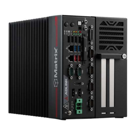
ADLINK Technology MXC-6600 Series User Manual (103 pages)
High Performance 9th Generation Intel Xeon/Core i7/i3 & 8th Gen Intel Core i5 Processor-Based Fanless Expandable Computer
Brand:
ADLINK Technology
| Category:
Desktop
| Size: 3 MB
Table of Contents
Table of Contents
5
List of Tables
7
List of Figures
9
1 Introduction
11
Overview
11
Features
11
Packing List
12
Optional Accessories
12
2 Specifications
13
MXC-662X/MXC-664X/MXC-6621/MXC-6641
13
MXC-6622/MXC-6642/MXC-6623/MXC-6643
15
MXC-6600 Series Functional Block Diagram
17
Figure 2-1: MXC-6600 Series Functional Block Diagram
17
Display Options
18
Table 2-1: Maximum Display Resolution Configurations
18
Mechanical Dimensions
19
Figure 2-2: MXC-6620 Front View
19
Figure 2-3: MXC-6640 Front View
20
Figure 2-4: MXC-6620/6640 Left Side View
21
Figure 2-5: MXC-6620/6640 Right Side View
22
Figure 2-6: MXC-6620/6640 Top View (with Wall-Mount Brackets)
23
3 System Layout
25
Front Panel
25
Table 3-1: Front Panel I/O Legend
25
Figure 3-1: Front Panel I/O
25
Table 3-2: LED Indicators
26
Table 3-3: Displayport Pin Definition
27
Figure 3-2: Displayport Connector Pin Definition
27
Table 3-4: Applicable Cable Types
28
Figure 3-3: Digital I/O Connector Pin Definition
28
Table 3-5: Digital Input/Output Connector Pin Definition
29
Figure 3-4: Digital Input Circuit
29
Table 3-6: HDMI Connector Pin Definition
30
Figure 3-5: Digital Output Circuit
30
Table 3-7: Ethernet Port Pin Definition
32
Table 3-8: Active/Link LED Indicators
32
Table 3-9: Speed LED Indicators
32
Figure 3-6: Ethernet Port and Leds
32
Table 3-10: DC Power Input Pin Definition
33
Figure 3-7: DC Power Input
33
Table 3-11: D-Sub 9-Pin Signal Function of COM Ports
34
Figure 3-8: COM Port Pin Definition
34
Figure 3-9: Cfast Host Slot
35
Internal I/O Connectors
36
Figure 3-10: Mainboard Connectors
36
Table 3-12: Mainboard Connector Legend
37
Table 3-13: 2-Slot Backplane Board Connector Legend
38
Figure 3-11: 2-Slot Backplane Board Connectors
38
Table 3-14: 4-Slot Backplane Board Connector Legend
39
Figure 3-12: 4-Slot Backplane Board Connectors
39
Table 3-15: GPS Module Power Header Pin Definition
40
Figure 3-13: GPS Module Power Header Pin Definition
40
Table 3-16: 12V Fan Connector Pin Definition
41
Figure 3-14: 12V Fan Connector Pin Definition
41
Figure 3-15: Clear CMOS Jumper Setting
41
Table 3-17: PWR/RESET Header Pin Definition
42
Table 3-18: 12V Power Pin Definition
42
Figure 3-16: PWR/RESET Header Pin Definition
42
Figure 3-17: 12V Power Pin Definition
42
4 Getting Started
43
Attach DC Power Connector
43
Mounting the MXC-6600 Series
44
Driver Installation
46
A Appendix: Power Consumption
47
Power Consumption Reference
47
Table A-1: Power Consumption
47
B Appendix: BIOS Setup
49
Main
50
Advanced
51
Chipset
66
Security
77
Boot
79
Save & Exit
81
C Appendix: Watchdog Timer (WDT) Function Library
83
WDT with Api/Windows
83
WDT with Dos/Linux
86
D Appendix: Digital Input/Output Function Library
89
Important Safety Instructions
97
Consignes de Sécurité Importante
99
Getting Service
103
Advertisement
Advertisement
Related Products
ADLINK Technology MXC-6300
ADLINK Technology MXC-6201D
ADLINK Technology MXC-6101D
ADLINK Technology MXC-6620
ADLINK Technology MXC-6640
ADLINK Technology Matrix MXC-4000 Series
ADLINK Technology Matrix MXC-4002D
ADLINK Technology MXC-2300
ADLINK Technology MXC-2300CD-3E1
ADLINK Technology MXC-2300-3E1
ADLINK Technology Categories
Computer Hardware
Motherboard
PCI Card
Control Unit
Desktop
More ADLINK Technology Manuals
Login
Sign In
OR
Sign in with Facebook
Sign in with Google
Upload manual
Upload from disk
Upload from URL