Table of Contents
Advertisement
Quick Links
Advertisement
Table of Contents

Related Manuals for CKD RLSH Series


Summary of Contents for CKD RLSH Series
- Page 1 GRIPPERS FOR COLLABORATIVE ROBOT RLSH SERIES RHLF SERIES RCKL SERIES INSTRUCTION MANUAL SM-A28840-A • Read this Instruction Manual before using the product. • Read the safety notes carefully. • Keep this Instruction Manual in a safe and convenient place for future reference.
- Page 2 • Since there are a wide variety of customer applications, it is impossible for CKD to be aware of all of them. Depending on the application or usage, the product may not be able to exercise its full performance or an accident may occur due to fluid, piping, or other conditions.
-
Page 3: Precautions On Product Use
• For applications where life or properties may be adversely affected and special safety measures are required. (Exception is made if the customer consults with CKD prior to use and understands the specifications of the product. However, even in that case, safety measures must be taken to avoid danger in case of a possible failure.) -
Page 4: Precautions On Product Disposal
SM-A28840-A PREFACE CAUTION When using the product in a cutting, casting, or welding plant, install a cover to prevent foreign matters such as cutting fluid, chips, powder, and dust from entering. Do not use the equipment in the following environments. •... -
Page 5: Table Of Contents
Using the gripper ....................12 3.1.1 Usage ......................12 3.1.2 Starting the robot ..................13 3.1.3 Software installation ..................13 3.1.4 Setting “CKD Pneumatic Gripper” ..............13 3.1.5 Adjustment of sencor ..................13 Program functions and operations ..............14 3.2.1 Software installation ..................14 3.2.2 Explanation of operation screen .............. -
Page 6: Contents
SM-A28840-A CONTENTS 5.1.2 Sensor ......................22 WARRANTY PROVISIONS ..................23 Warranty Conditions .................... 23 Warranty Period ....................23 2020-02-24... -
Page 7: Product Overview
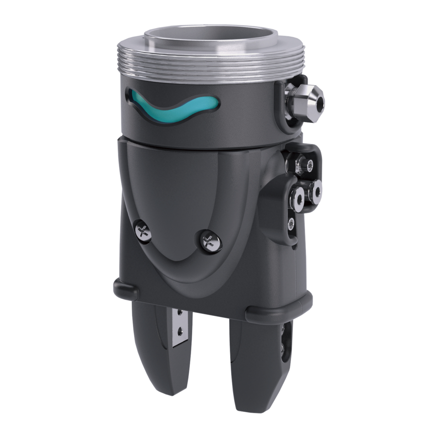
SM-A28840-A 1. PRODUCT OVERVIEW 1. PRODUCT OVERVIEW 1.1 Model Number Indication 1.1.1 RLSH Series R L S H – A 2 0 D 1 N – L 1 – Y 2 V – U R (B)Attachments (A)Robot flange Code Content... -
Page 8: Rckl Series
SM-A28840-A 1. PRODUCT OVERVIEW 1.1.3 RCKL Series R C K L – 4 0 C S – – U R (B)Attachments (A) Robot flange Code Content (A) Robot Flange Blank Without Robot flange With Robot flange (Note 1) Symbol Content Attachments Blank Without attchments... -
Page 9: Speciffications
SM-A28840-A 1. PRODUCT OVERVIEW 1.2 Speciffications 1.2.1 RLSH Series Specification Descriptions RLSH Cylinder bore size φ20 Actuation Double acting Working fluid Compressed air Max.working pressure air Min.working pressure air Applicatable tube outer diameter φ4 Port size (Tube size) (With speed control valve)... -
Page 10: Rhlf Series
SM-A28840-A 1. PRODUCT OVERVIEW 1.2.2 RHLF Series Specification Descriptions RHLF Cylinder bore size φ16×2 Actuation Double acting Working fluid Compressed air Max.working pressure air Min.working pressure air Applicatable tube outer diameter φ4 Port size(Tube size) (With speed control valve) Ambient temperature 5 〜... -
Page 11: Rckl Series
SM-A28840-A 1. PRODUCT OVERVIEW 1.2.3 RCKL Series Specification Descriptions RCKL Cylinder bore size φ40 Actuation Double acting Working fluid Compressed air Max.working pressure air Min.working pressure air Applicatable tube outer diameterφ4 Port size(Tube size) (With speed control valve) Ambient temperature 5 〜... -
Page 12: Electrical Circuit Diagram
SM-A28840-A 1. PRODUCT OVERVIEW 1.3 Electrical Circuit Diagram Electrical circuit diagram Indicator lamp inside flange Tool connector 1.4 Dimensions 1.4.1 RLSH Series 2020-02-24... -
Page 13: Rhlf Series
SM-A28840-A 1. PRODUCT OVERVIEW 1.4.2 RHLF Series 1.4.3 RCKL Series 2020-02-24... -
Page 14: Installation
SM-A28840-A 2. INSTALLATION 2. INSTALLATION 2.1 Environment CAUTION When using the product in a cutting, casting, or welding plant, install a cover to prevent foreign matters such as cutting fluid, chips, powder, and dust from entering. Do not use the equipment in the following environments. •... -
Page 15: Body
The effect on the hand body must be taken into consideration when mounting the attachment to the finger. Support the attachment with a wrench when tightening it so as not to twist the finger. Do not apply load to the body Tightening torque(N・m) Descriptions Bolt used RLSH Series M4×0.7 RHLF Series M4×0.7 RCKL Series M5×0.8 2020-02-24... -
Page 16: Sensor
SM-A28840-A 2. INSTALLATION Lateral load Be careful not to apply a lateral load to the finger when mounting the attachment. Finger Attachment Finger Attachment Backlash or damage may occur when an excessive lateral load or an impact load is applied. Use the product so that the external force applied to the finger does not exceed the allowable load described in the catalog. -
Page 17: Piping
SM-A28840-A 2. INSTALLATION Wiring of valve and controller Connect the valve wiring to the I/O terminal set on the previous page. In the case of the figure below, the “Open” signal is connect to {Digital Output [1]}, and the “Close”... -
Page 18: Usage
SM-A28840-A 3. USAGE 3. USAGE 3.1 Using the gripper CAUTION Make sure that no excessive load is applied to the fingers and claws during work removal and transfer. The linear rolling surface of the finger may be damaged or dented, resulting in malfunction. 3.1.1 Usage Supply air to the valve. -
Page 19: Starting The Robot
Turn on the robot. (For details, see the robot manual.) 3.1.3 Software installation Insert the included USB into the teachpendant and install the software. Software : CKD Pneumatic Gripper For details , see the “Installation of 「3.2.1Software installation 」. 3.1.4 Setting “CKD Pneumatic Gripper”... -
Page 20: Program Functions And Operations
On the teachpendant of the UR robot, go to the [ Setup Robot ] screen and select [ URCaps ] . Select the [+] button on the screen, select [ CKD Pneumatic Gripper ] from data in USB, and press [ OPEN ] . -
Page 21: Explanation Of Operation Screen
Note : For details on how to use [ URCaps ], refer to the UR robot manual. 3.2.2 Explanation of operation screen Setting screen The setting screen is displayed by pressing [ CKD Pneumatic Gripper ] under the [ installation ]. No.3 No.1 No.4... - Page 22 Light blue Cylinder Position Sensors Proguram registratio Display when select [ Program ], and select [ Structure ], and select [ URCaps ], press [ CKD Pneumatic Gripper ], and press “ CKD Gripper” on the program list. No.1 Select No.2...
- Page 23 Note 1: The setting on the [CKD Pneumatic Gripper ] screen is available only for “Close”. At the time of “Open” makes setting on the UR robot default setting screen shwn below.
-
Page 24: Program Setting Procedure
SM-A28840-A 3. USAGE 3.2.3 Program setting procedure After setting up the UR robot and connecting this product, set up the software. Go to the [ Installation ] tab, Set the [ Tool output voltage ] to 24V. Set the “Open” signal and “Close” signal on the setting screen. The figure below shows the case where the {digital output [1]}... -
Page 25: Procedure For Registering Commands In The Program
After completing the software setting, register the command in the UR robot program. If you select [ Structure ] tab, [ URCaps ] tab, and press [ CKD Pneumatic Gripper ] on the program screen, CKD Grip: will be added to the UR robot program list displayed on the left side of the screen. - Page 26 SM-A28840-A 3. USAGE Press the button of Open” or “Close” on the [ CKD Pneumatic Gripper ] screen, and the name of program is changed, and the command is registered in the UR robot program. Sensor status and gripper display...
-
Page 27: Maintenance And Inspecion
SM-A28840-A 4. MAINTENANCE AND INSPECION 4. MAINTENANCE AND INSPECION WARNING Do not touch electrical wiring connections (bare live parts) of actuators equipped with solenoid valves, actuators equipped with switches, and other such actuators. Do not touch live parts with bare hands. An electric shock may occur. -
Page 28: Troubleshooting
Ambient temperature is too high or too low. to 60° Magnetic field is nearby. Install a magnetic shield. External signal is faulty. Check the external circuit. If you have any other questions or concerns, contact your nearest CKD sales office or distributor. 2020-02-24... - Page 29 Warranty coverage If the product specified herein fails for reasons attributable to CKD within the warranty period specified below, CKD will promptly provide a replacement for the faulty product or a part thereof or repair the faulty product at one of CKD’s facilities free of charge.
Need help?
Do you have a question about the RLSH Series and is the answer not in the manual?
Questions and answers