Table of Contents
Advertisement
Quick Links
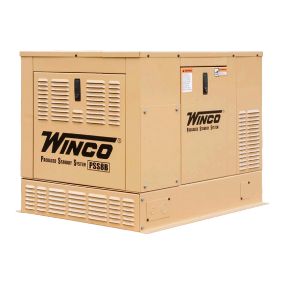
PSS8B2W/F
GENERATOR
INSTALLATION & OPERATORS
MANUAL
COPY YOUR MODEL AND SERIAL NUMBER HERE
No other WINCO generator has the same serial number as yours.
If you should ever need to contact us concerning this unit, it will
help us to respond to your needs faster.
MODEL _________________________________________________
SERIAL NUMBER _________________________________________
PURCHASE DATE _________________________________________
DEALER NAME ___________________________________________
DEALER PHONE # ________________________________________
www.wincogen.com
Advertisement
Table of Contents

Related Manuals for Winco PSS8B2W/F


Summary of Contents for Winco PSS8B2W/F
- Page 1 MANUAL COPY YOUR MODEL AND SERIAL NUMBER HERE No other WINCO generator has the same serial number as yours. If you should ever need to contact us concerning this unit, it will help us to respond to your needs faster.
-
Page 2: Table Of Contents
Should you experience a problem please follow the “Troubleshooting Tables” near the end of this manual. The warranty listed in the manual describes what you can expect from WINCO should you need service assistance in the future. 60706-211/F... -
Page 3: Safety Information
SAFETY INFORMATION E. Store fuel only in an approved container, and only in a well ventilated area. This engine generator set has been designed and F. Follow local codes for closeness to combustible manufactured to allow safe, reliable performance. Poor material. -
Page 4: Specifications
SPECIFICATIONS INTRODUCTION GENERATOR PRODUCT DESCRIPTION Fuel Watts* Volts Amps The package standby system is designed to automatically 8,400 120/240 35 3600 provide standby power to unattended loads during electrical outages. Upon interruption of normal electrical 7,600 120/240 32 3600 service, the packaged standby system electrical control *Continuous rating. -
Page 5: Preparing The Unit
1. As you receive your unit, it is critical to check it for any requirements. damage. If any damage is noted, it is always easiest to refuse the shipment and let WINCO take care of the freight FUEL INSTALLATION claim. If you sign for the unit, the transfer of the ownership... -
Page 6: Natural Gas (Ng)
FUEL PRESSURE operating pressure. This low pressure regulator must be at least 10 feet from the engine generator set; any closer installation will require a larger line be installed to provide Correct fuel pressure cannot be stressed enough. The most a fuel reservoir. -
Page 7: Fuel Pressure Tables
FUEL PRESSURE TABLES LUBRICATION The following tables are the fuel pressure readings at each Before starting the engine, fill the crankcase to the proper reference in the system. level with a good quality oil. The recommended grade oil and quantity of oil required is listed in the engine operator’s Single low pressure regulator (LP vapor only) manual and under the service tab in this manual. -
Page 8: Installing The Battery
CAUTION: EQUIPMENT DAMAGE 2. Where electrolyte contacts skin, wash off immediately Allowing the engine to shutdown repeatedly on low oil with water. level may cause excessive wear which can be cumulative. 3. If electrolyte contacts the eyes, flush immediately and thoroughly with water. -
Page 9: Connecting The Battery Charger
The WINCO solar option consists of two parts; one the solar panel and two the Sun Guard charge controller. The solar The battery tender receptacle is to be powered by a GFCI... -
Page 10: Dc Electrical Interconnection
Suggested circuits: freezer, refrigerator, furnace, emergency lights, sump pump, emergency outlet WINCO UL ATS (ASCO 185) circuits, etc. Total running load must not exceed generator rating. See the ASCO installation manual for additional details on proper wiring of the Automatic Transfer Switch. -
Page 11: Initial Start Up
INITIAL START UP itch, h cold INITIAL START UP STOP/RESET (red button) - This button places WARNING: the module into its Stop/Reset mode. This will clear any alarm conditions for which the DO NOT jump start these engine generator sets. Starting these units WARNING: triggering criteria have been removed. - Page 12 EXERCISE WITH OR WITHOUT LOAD The transfer switch can be set up to exercise the generator CAUTION: with or without a load transfer. Normally, WINCO Before using the transfer test button, be sure that generators exercise without a load transfer. This is because...
-
Page 13: Customer Connection Area
CUSTOMER CONNECTION AREA Function Factory Actuator Setting Switch Actuator Position START & FUEL RELAYS Clock On (up) ENGINE LOCATED IN CONTROL Battery Off (down) BACK MODULE On (up) ASSEMBLY Exerciser Off (down) With load With (up) Without or without Without Load load (down) -
Page 14: Sequence Of Operation
SEQUENCE OF OPERATION UTILITY FAILURE 60706-211/F... -
Page 15: Dse 3110
DSE 3110 DSE 3110 FAULT CODES FRONT PANEL CONFIGURATION Auxiliary inputs can be user configured and will display he message as written by the user. Fail to Start. The engine has not fired after the preset number of start attempts. Fail to Stop. -
Page 16: Dse 3110 Engine Control
PREVENTATIVE MAINTE- DSE 3110 ENGINE CONTROL NANCE PROTECTIONS When an alarm is present, the Common alarm LED (if Reasonable care in preventative maintenance will ensure configured) will illuminate. The LCD display will show an icon high reliability and a long life for the engine-generator set to indicate the failure. -
Page 17: Engine Maintenance
ENGINE MAINTENANCE MAINTENANCE SCHEDULE Every 8 Hours or Daily CHECKING THE OIL LEVEL • Check engine oil level The oil level must always be checked before the engine is • Clean area around muffler and controls started. Every 100 Hours or Annually •... -
Page 18: Trouble Shooting
TROUBLE SHOOTING WARNING: Never jump start these units. Jump starting these units with low or bad batteries will cause permanent damage to the engine control module. ATS PANEL WILL NOT PULL IN ON NORMAL POWER UNIT WILL NOT CRANK WHEN THE POWER FAILS 1. -
Page 19: Outline Drawing
OUTLINE DRAWING 36.50 28.00 28.375 27.375 29.75 36.00 60706-211/F... -
Page 20: Pad Layout Drawing
ENGINE GENERATOR SET PAD LAYOUT DRAWING PAD LAYOUT AC WIRING SCHEMATIC 60706-211/F... -
Page 21: Ac And Dc Generator Schematic
AC AND DC GENERATOR SCHEMATIC 60706-211/F 11075-00 60706-211... -
Page 22: Solar Control Panel
SOLAR CONTROL PANEL (IF EQUIPPED) EXTERNAL RECEPTICAL ASSEMBLY (IF EQUIPPED) 60706-211/F... -
Page 23: Solar Panel Assembly
SOLAR PANEL ASSEMBLY (IF EQUIPPED) 60706-211/F... -
Page 24: 12 Month Limited Warranty
WINCO written instructions and applicable codes. WINCO’s sole liability, and Purchaser’s sole remedy for a failure under this warranty, shall be limited to the repair of the product. At WINCO’s option, material found to be defective in material or workmanship under normal use and service will be repaired or replaced.
Need help?
Do you have a question about the PSS8B2W/F and is the answer not in the manual?
Questions and answers