Table of Contents
Advertisement
Quick Links
Advertisement
Table of Contents

Related Manuals for Winco PSS60F4 1 Series


Summary of Contents for Winco PSS60F4 1 Series
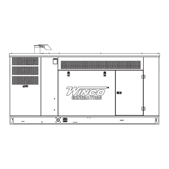
- Page 1 PSS60F4-XX/1 GENERATOR INSTALLATION AND OPERATORS MANUAL www.wincogen.com...
-
Page 2: Table Of Contents
TABLE OF CONTENTS MAINTENANCE SAVE THESE INSTRUCTIONS CHANGING COOLANT SAFETY INFORMATION COOLANT FILL & BURP INSTRUCTIONS SAFETY DEFINITIONS CLEANING RADIATOR SPECIFICATIONS STORAGE PSS60F4 AUTOMATIC TRANSFER SWITCH INTRODUCTION MAINTENANCE SCHEDULE TESTING POLICY ENGINE-GENERATOR SET PRODUCT DESCRIPTION TROUBLESHOOTING TABLES PREPARING THE UNIT AC WIRING START-UP CHECK LIST ENGINE HARNESS SCHEMATIC... -
Page 3: Save These Instructions
COPY YOUR MODEL AND SERIAL NUMBER HERE No other WINCO generator has the same serial number as yours. If you should ever need to contact us on this unit, it will help us to respond to your needs faster. -
Page 4: Safety Information
SAFETY INFORMATION IMPORTANT SAFETY INSTRUCTIONS DANGER: FIRE HAZARD This engine generator set has been designed and Gasoline and other fuels present a hazard of possible manufactured to allow safe, reliable performance. Poor explosion and/or fire. maintenance, improper or careless use can result in A. -
Page 5: Specifications
SPECIFICATIONS PSS60F4 LP Gas - Standby Wattage 60,000 62,000 62,000 62,000 62,000 Volts 120/240 120/208 120/240 277/480 346/600 60.0 77.5 77.5 77.5 77.5 Phase Single Three Three Three Three Amps CB Size Hertz Natural Gas - Standby Wattage 60,000 62,000 62,000 62,000 62,000... -
Page 6: Introduction
Go to the WINCO website (wincogen.com) Rated output of generator is based on engineering tests for a list of engine dealers or contact the WINCO Service of typical units, and is subject to, and limited by, the Department. -
Page 7: Preparing The Unit
If any damage is noted, it is easiest to refuse the shipment and let WINCO take care of the freight claim. If you sign for the unit, the transfer of the ownership requires that you file the freight claim 2. -
Page 8: Installation
INSTALLATION system installation. The information in this manual is offered This unit should be installed in a well ventilated area, ensuring the exhaust air cannot be recirculated back into only as a guide to finalizing your installation plans. the engine. WARNING: PERSONAL INJURY CAUTION: The enclosures on these units can become very hot... -
Page 9: Exhaust Installation
WARNING: FIRE HAZARD Discharge All fuel runs should be installed by a licensed fuel supplier. The WINCO installation manual OPM-112 contains additional information on indoor, open skid installations To connect the fuel line to the generator set you will and is available electronically through our website or by connect your incoming fuel line to the 1.25 inch NPT... -
Page 10: Natural Gas (Ng)
a larger line be installed to provide a fuel reservoir. This is interfere with each other. This regulator must be sized to also true for the single low pressure regulator, it should accommodate the demand of the generator set and any also be a minimum of 10 feet from the unit. -
Page 11: Fuel Pressure Tables
NG/LP FUEL CONVERSION Reference in both diagrams: numbers 1 through 3 in the diagram above are system parts supplied by the customer. Reference number 4 is on the generator. This generator set was tested on both LP and NG at the The following diagram is of a natural gas (NG) installation. -
Page 12: Electrical Connections
ELECTRICAL CONNECTIONS For additional information on wire sizing refer to table 310- AC ELECTRICAL CONNECTIONS 16 of the National Electrical Code ANSI/NFPA 70. C - Ground Lug, These ground lugs are bonded to ground NOTICE: CLASS 1 WIRING METHODS ARE TO BE USED and are provided for you to connect your ground wire FOR ALL FIELD WIRING CONNECTIONS TO TERMINAL OF from the transfer switch to. -
Page 13: Transfer Switch
TRANSFER SWITCH below the engine control cabinet. NOTICE For full service switching of the entire load, the ATS must be ‘SE’ (Service Entrance) rated or must have a properly rated fusible disconnect installed before the ATS to protect the contacts. ASCO 185 UL SWITCH Your DC connection points in the ASCO 185 UL ATS are on the terminal block on the bottom of the controller in the... -
Page 14: Mounting The Ats
MOUNTING THE ATS furnace, emergency lights, sump pump, emergency outlet circuits, etc. Total running load must not exceed generator rating See the ASCO installation manual for additional details on proper wiring of the Automatic Transfer Switch. WARNING: FIRE HAZARD All wiring must be done by a licensed electrician, and must conform to the National Electrical Code and comply with all the local codes and regulations. -
Page 15: Installing The Battery
INSTALLING THE BATTERY CAUTION WARNING In the following battery installation procedure, check to The electrolyte is a diluted sulfuric acid that is harmful be sure the engine control is in the “stop” position. This to the skin and eyes. It is electrically conductive and should be your last step before initial start-up. -
Page 16: Battery Charger & Block Heater
CAUTION: EQUIPMENT DAMAGE NEVER JUMP START these units. Doing so will destroy the engine control module, rendering the unit non- operational. Remove and fully recharge the battery before attempting to start. BATTERY CHARGER & BLOCK HEATER BATTERY CHARGER A three-stage, on-board marine battery charger is provided standard on this unit. -
Page 17: Starting Procedure
F-153 Pre-Start & Warranty Form was sent with your generator. This form must be filled out by an Authorized WINCO Service Center and submit it to our WINCO Service Department for your warranty to become valid. After completing the checklist, the engine-generator set is ready for initial start-up. -
Page 18: Control Layout
CONTROL LAYOUT fault condition is removed. The icon will appear steady in the display. SHUTDOWN Shutdowns are critical alarm conditions that stop the engine and draw the operator’s attention to an undesirable condition. Shutdown alarms are latching. The fault must be removed and the STOP/RESET button pressed to reset the module. -
Page 19: Auto Mode
WARNING: EQUIPMENT DAMAGE Failure to insure proper rotation will cause three phase motors to spin backwards, possibly causing damage to the equipment. NOTICE If for any reason during the check out procedure the voltage and frequency are not correct, depress the STOP/ RESET button and correct the trouble before proceeding. -
Page 20: Voltage Regulator
VOLTAGE REGULATOR OPERATING CONDITIONS The following is a list of connections on the AVR. These NORMAL OPERATION have been factory set and other than voltage adjustment, should never be changed. This generator-engine set needs load and should not idle for long periods of time. AS440 AVR If the generator application is for emergency standby the generator should be exercised at least monthly ideally... -
Page 21: Changing The Oil
2. Place a drip pan or suitable container for catching the the level is between the maximum and minimum lines oil . WINCO has supplied a valve on the skid frame to shown on the dipstick. hook a customer supplied 5/8” hose to conveniently run the oil to the drip pan. -
Page 22: Changing Coolant
7. Fill the remaining amount of coolant needed in the radiator. Replace cap. 8. Run the engine to check for leaks. COOLANT FILL & BURP INSTRUCTIONS 1. Engine should be cooled down to at least 110˚F 2. Ensure the radiator plug located at the bottom of the 1. Make sure engine is plumbed and all drains/petcocks are radiator and the plug on the engine block are secure. -
Page 23: Cleaning Radiator
7. Test run and inspect for any leaks/verify unit is not 3. If engine is less transmission, spray flywheel and ring overheating. gear with mixture of one part recommended engine oil, and one part Stoddard Solvent or equivalent. CLEANING RADIATOR 4. -
Page 24: Maintenance Schedule
ENGINE-GENERATOR SET MAINTENANCE SCHEDULE Service the engine in accordance with the engine DAILY manufacturer’s manual provided with your new equipment. Check Engine Oil Level/Replenish if Needed Routinely remove debris and dirt from around the inside generator enclosure. Ensure that the air intakes are free Check Coolant Level/Replenish if Needed from leaves and other debris at all times. -
Page 25: Troubleshooting Tables
TROUBLESHOOTING TABLES UNIT WILL NOT 1. Digital genset controller not in “AUTO” CRANK WHEN THE 2. Transfer control switch not in “AUTOMATIC”. POWER FAILS 3. Incorrect wiring between transfer switch and generator. 4. Loose or dirty battery terminals. 5. Defective engine control module. 6. -
Page 26: Ac Wiring
THREE PHASE AC WIRING HIGH AND LOW WYE HIGH AND LOW WYE AC WIRING THREE PHASE-HIGH WYE THREE PHASE-LOW WYE THREE PHASE-HIGH WYE 277/480 VOLTS THREE PHASE-LOW WYE 120/208 VOLTS 277/480 VOLTS 120/208 VOLTS THREE PHASE - HIGH WYE 277/480V THREE PHASE - LOW WYE 120/208V THREE PHASE AC SINGLE PHASE AC... -
Page 27: Engine Harness Schematic
ENGINE HARNESS SCHEMATIC OPM-160/B... -
Page 28: Dse 7310 Mkii Wiring Diagram
DSE 7310 MKII WIRING DIAGRAM OPM-160/B... -
Page 29: Warranty Statement
Air cooled units purchased for stock have 1 year to be sold. The warranty to the original retail customer commences on the date of sale of the product to them. All liquid cooled units have 180 days from the Winco invoice to submit a start up date. - Page 30 Standby use is defined as an application where utility power is present -and- the generator set is used as emergency backup during utility power outages. WINCO reserves the right to change or improve it’s products without incurring any obligations to make such changes or improvements on products purchased previously.
- Page 31 22. Travel time or service calls unless specifically authorized by Winco, Inc. in writing. GENERAL INFORMATION The WINCO, Inc. Service Department is open from 7:30 AM to 4:30 PM Central Standard time. It is located at 225 South Cordova Ave., Le Center, MN, 56057-1805. Phone Numbers: Service Department - 507-357-6831 FAX Line - 507-357-4857.
- Page 32 225 S. CORDOVA AVE • LE CENTER, MN 56057 Sales: 507-357-6821• sales@wincogen.com Service: 507-357-6831 • service@wincogen.com www.wincogen.com OPM-160/B...
Need help?
Do you have a question about the PSS60F4 1 Series and is the answer not in the manual?
Questions and answers