
Related Manuals for Emerson Rosemount 1154DH


Summary of Contents for Emerson Rosemount 1154DH
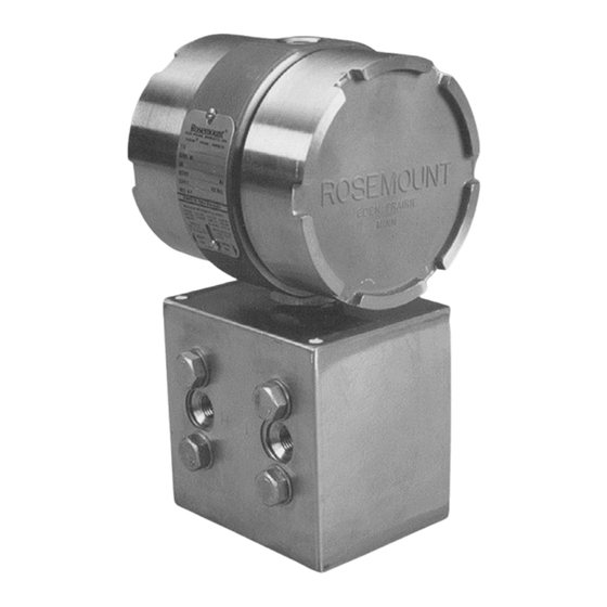
- Page 1 Reference Manual 00809-0100-4631, Rev BA April 2007 Rosemount 1154 Series H ® Alphaline Nuclear Pressure Transmitter Product Discontinued www.emersonprocess.com/rosemount/nuclear...
- Page 2 Amplifier Circuit Board, Output Code R, N0026: In all locations, replaced “01154-0001-0006” with “01154-0153-0002” 6-11 Table 6-2, “Parts List Rosemount 1154DH, 1154HH, and 1154SH”, in all locations the 6/9/17 following part numbers are updated: Amplifier Circuit Board, Output Code R: “01154-0153-0001”...
- Page 3 Reference Manual 00809-0100-4631, Rev BA Rosemount 1154 Series H April 2007 Rosemount 1154 Series H ® Alphaline Pressure Transmitters NOTICE Read this manual before working with the product. For personal and system safety, and for optimum product performance, make sure you thoroughly understand the contents before installing, using, or maintaining this product.
- Page 4 Reference Manual 00809-0100-4631, Rev BA Rosemount 1154 Series H April 2007 Rosemount Nuclear Instruments, Inc. Warranty and Limitations of Remedy The warranty and limitations of remedy applicable to this Rosemount equipment are as stated on the reverse of the current Rosemount quotation and customer acknowledgment forms. RETURN OF MATERIAL Authorization for return is required from Rosemount Nuclear Instruments, Inc.
- Page 5 Replaced amplifier circuit board with damping, output code R P/N 01154-0021-0002 with 01154-0021-0004. Replaced amplifier circuit board for N0026, output code R P/N 01154-0001-0002 with 01154-0001-0006. Throughout Throughout References to Fisher-Rosemount were changed to Emerson Process Management. i, back Cover, i, ii Web address changed from www.rosemount.com to www.emersonprocess.com/rosemount/nuclear.
- Page 6 Reference Manual 00809-0100-4631, Rev BA Rosemount 1154 Series H April 2007...
-
Page 7: Table Of Contents
Correction For High Line Pressure (Rosemount 1154DH and 1154HH only)....3-6 Span ..........3-7 Zero . - Page 8 Reference Manual 00809-0100-4631, Rev BA Rosemount 1154 Series H April 2007 Sensing Module Checkout........5-2 Disassembly Procedure.
- Page 9 Reference Manual 00809-0100-4631, Rev BA Rosemount 1154 Series H April 2007 Physical Specifications ........6-6 Materials of Construction.
- Page 10 Reference Manual 00809-0100-4631, Rev BA Rosemount 1154 Series H April 2007 TOC-4...
-
Page 11: Overview
Reference Manual 00809-0100-4631, Rev BA Rosemount 1154 Series H April 2007 Section 1 Introduction OVERVIEW This manual is designed to assist in installing, operating, and maintaining the Rosemount 1154 Series H Alphaline® Nuclear Pressure Transmitter. The manual is organized into the following sections: Section 2: Installation Provides general, mechanical, and electrical installation considerations to guide you through a safe and effective transmitter installation. - Page 12 Reference Manual 00809-0100-4631, Rev BA Rosemount 1154 Series H April 2007...
-
Page 13: Overview
Reference Manual 00809-0100-4631, Rev BA Rosemount 1154 Series H April 2007 Section 2 Installation Overview ........page 2-1 General Considerations . -
Page 14: Mechanical Considerations
Reference Manual 00809-0100-4631, Rev BA Rosemount 1154 Series H April 2007 Figure 2-1. Qualified Life vs. Ambient Temperature. Module Qualified Life Electronics Qualified Life Ambient Temperature (°F) MECHANICAL This section contains information you should consider when preparing to mount the transmitter. Read this section carefully before proceeding to the CONSIDERATIONS mechanical installation procedure. - Page 15 Reference Manual 00809-0100-4631, Rev BA Rosemount 1154 Series H April 2007 Process tubing used is in. outside diameter, and of suitable thickness for the pressure involved. The Swagelok tube fittings are shipped completely assembled for immediate use. Do not disassemble them before use; doing so may contaminate the fittings and result in leaks.
-
Page 16: Conduit
Reference Manual 00809-0100-4631, Rev BA Rosemount 1154 Series H April 2007 The piping between the process and the transmitter must transfer the pressure measured at the process taps to the transmitter. Possible sources of error in this pressure transfer are: •... - Page 17 Reference Manual 00809-0100-4631, Rev BA Rosemount 1154 Series H April 2007 Signal wiring need not be shielded, but twisted pairs should be used for best results. In electrically noisy environments, shielded cable should be used for best results. Do not run signal wiring in conduit or open trays with power wiring, nor near heavy electrical equipment.
-
Page 18: Installation Procedures
Reference Manual 00809-0100-4631, Rev BA Rosemount 1154 Series H April 2007 INSTALLATION Installation consists of mounting the transmitter and conduit and making electrical connections. Following are procedures for each operation. PROCEDURES Mechanical Transmitter Be careful not to break the neck seal between the sensor module and the electronics housing. - Page 19 Reference Manual 00809-0100-4631, Rev BA Rosemount 1154 Series H April 2007 Figure 2-4. Typical Transmitter Mounting Bracket Configuration. Center of Gravity (bracket included) 0.06 (1.5) 1.31 (30.5) 7.55 (191.8) 4.93 2.81 (125) (71.4) 2.81 (71.4) in. Bolts (4) (customer 2.75 supplied) (69.9) 10 (254) Minimum Clearance...
- Page 20 Reference Manual 00809-0100-4631, Rev BA Rosemount 1154 Series H April 2007 Figure 2-5. Transmitter Dimensional Drawings. ROSEMOUNT 1154DH AND 1154HH 4.7 Max. 4.72 Max. 0.75 (19) - 14 NPT (119.4) (119.9) clearance for Conduit cover connection removal (1 Place) Nameplate...
-
Page 21: Conduit
Manifold Flow Flow Drain/Vent Drain/Vent Valves Valve Rosemount 1154DH, HH Rosemount 1154SH Rosemount 1154SH Rosemount 1154DH, HH Electrical Remove the cover from the terminal side of the transmitter (see Figure 2-5 on page 2-8). Connect the power leads to the “SIGNAL” terminals on the transmitter terminal block (see Figure 2-7 on page 2-10). - Page 22 Reference Manual 00809-0100-4631, Rev BA Rosemount 1154 Series H April 2007 Figure 2-7. Transmitter Terminal Block. Signal Terminals Test Terminals 2-10...
-
Page 23: Overview
Correction for High Line Pressure CALIBRATION The Rosemount 1154DH, HH, and SH transmitters are factory calibrated to the range shown on the nameplate. This range may be changed within the limits of the transmitter. Zero may also be adjusted to elevate or suppress. -
Page 24: Calibration Procedure
Reference Manual 00809-0100-4631, Rev BA Rosemount 1154 Series H April 2007 Figure 3-1. Zero Adjustment Range. Output 600% Zero Elevation (mA) –125 –100 –75 –50 –25 –150 Pressure (inH ➀ 600% Zero Elevation Output (mA) Pressure (inH ➀ No Zero Elevation or Suppression 500% Zero Suppression Output (mA) - Page 25 Reference Manual 00809-0100-4631, Rev BA Rosemount 1154 Series H April 2007 Figure 3-2. Zero and Span Adjustment Screws. Zero Screw Span Screw Example (for Range Code 4) Initial transmitter calibration: 25 to 125 inH O (100 inH O span with zero suppressed 25 inH Desired transmitter calibration: –75 to –25 inH O (50 inH...
-
Page 26: Material
Reference Manual 00809-0100-4631, Rev BA Rosemount 1154 Series H April 2007 Since the span adjustment affects zero one-fifth as much as the span, the 0.125 mA increase in span causes a 0.025 mA increase in zero. Therefore, turn the zero adjustment (at 50 inH O) until the output reads 20.000 mA. -
Page 27: Linearity Adjustment
Reference Manual 00809-0100-4631, Rev BA Rosemount 1154 Series H April 2007 Figure 3-3. Jumper Wire DETAIL A DETAIL B DETAIL C Placement. Moderate (To Elevate Zero) (To Suppress Zero) Elevation/ Suppression (No Jumper Wire) Jumper Wire Jumper Wire Linearity Adjustment In addition to the span and zero adjustments, there is a linearity adjustment located inside the transmitter on the amplifier board (see Figure 3-4 on page 3-6). -
Page 28: Damping Adjustment
Reference Manual 00809-0100-4631, Rev BA Rosemount 1154 Series H April 2007 Figure 3-4. Linearity and Damping Adjustment. Damping Adjustment (optional) Linearity Adjustment Electronics Side of Transmitter Housing (cover removed) Damping Adjustment Damping electronics are available as an option. Transmitters with standard electronics can be retrofitted with the adjustable damping feature by changing out both the amplifier board (RMT P/N 01154-0021-0004) and the calibration board (RMT P/N 01154-0023-0002). -
Page 29: Span
Reference Manual 00809-0100-4631, Rev BA Rosemount 1154 Series H April 2007 Span Range Codes 4, 5, and 8: +0.75% of input/1,000 psi Range Codes 6 and 7: +1.25% of input/1,000 psi The correction procedure below uses the following example: Range Code 5, calibrated at –100 to 300 inH O to be operated at 1,200 psi line pressure. -
Page 30: Zero
Reference Manual 00809-0100-4631, Rev BA Rosemount 1154 Series H April 2007 11. Readjust zero and span adjustments for corrected outputs: 3.964 mA at –100 inH 20.108 mA at 300 inH There is an uncertainty of ±0.5 percent of input reading per 1,000 psi associated with the span correction. -
Page 31: Overview
Reference Manual 00809-0100-4631, Rev BA Rosemount 1154 Series H April 2007 Section 4 Operation Overview ........page 4-1 Transmitter Operation . - Page 32 Reference Manual 00809-0100-4631, Rev BA Rosemount 1154 Series H April 2007 is a constant. is the capacitance between the high pressure side and the sensing diaphragm. is the capacitance between the low pressure side and the sensing diaphragm. -------------------- – Where: is the current source.
-
Page 33: The -Cell Sensor
Reference Manual 00809-0100-4631, Rev BA Rosemount 1154 Series H April 2007 Figure 4-2. Electrical Block Diagram. CURRENT DEMODULATOR SENSOR DETECTOR TEST CURRENT LIMITER OSCILLATOR SIGNAL CURR. OSC. CONTROL VOLTAGE CONTROL AMP. REVERSE REGULATOR AMP. POLARITY PROTECTION CURRENT CONTROL ™ THE -CELL SENSOR Process pressure is transmitted through an isolating diaphragm and silicone -Cell... -
Page 34: Voltage Regulator
Reference Manual 00809-0100-4631, Rev BA Rosemount 1154 Series H April 2007 The sensing element capacitance is variable. Therefore, the frequency is variable about a nominal value of 32 kHz. An integrated circuit amplifier is used as a feedback control circuit and controls the oscillator drive voltage such that: -------------------- –... -
Page 35: Overview
Reference Manual 00809-0100-4631, Rev BA Rosemount 1154 Series H April 2007 Section 5 Maintenance and Troubleshooting Overview ........page 5-1 Safety Messages . -
Page 36: Safety Messages
Reference Manual 00809-0100-4631, Rev BA Rosemount 1154 Series H April 2007 SAFETY MESSAGES Instructions and procedures in this section may require special precautions to ensure the safety of the people performing the operations. Information that raises potential safety issues is indicated by a warning message. The following warning messages appear in this section. -
Page 37: Disassembly Procedure
Reference Manual 00809-0100-4631, Rev BA Rosemount 1154 Series H April 2007 Disengage the header assembly board (4) as described in Step 4 of the electrical housing disassembly procedure on page 5-3. You need not remove the module shroud from the electrical housing for checkout. -
Page 38: Removing Module Shroud From Electrical Housing
Reference Manual 00809-0100-4631, Rev BA Rosemount 1154 Series H April 2007 Removing Module Remove amplifier board and calibration board as described in the Electrical Housing Disassembly Section above. Shroud From Electrical Housing Loosen the lock nut (9). Unscrew the module shroud (8) from the electronics housing, simultaneously turning the header board and leads to prevent them from being twisted or damaged. -
Page 39: Electrical Housing Reassembly
Reference Manual 00809-0100-4631, Rev BA Rosemount 1154 Series H April 2007 Electrical Housing Replace the zero and span adjustment screw O-rings (11) whenever you remove the zero or span adjustment screws (10). Lightly grease Reassembly the O-rings with Dow Corning 55 Silicone O-ring Grease, (Rosemount P/N 01153-0248-0001). - Page 40 Reference Manual 00809-0100-4631, Rev BA Rosemount 1154 Series H April 2007 Figure 5-2. Exploded View Parts Drawing, Rosemount 1154 Series H. Table 5-1. Rosemount 1154 Series H Parts List. Part Description Part Description Electronics Cover Module Shroud O-Ring for Electronics Cover Module Shroud Lock Nut Electronics Housing Zero and Span Adjustment Screws...
-
Page 41: Troubleshooting
Reference Manual 00809-0100-4631, Rev BA Rosemount 1154 Series H April 2007 TROUBLESHOOTING Table 5-3. Troubleshooting. Symptom Potential Source Corrective Action High Output Primary Element Check for restrictions at primary element, improper installation or poor condition. Note any changes in process fluid properties. Impulse Piping Check for leaks or blockage. - Page 42 Reference Manual 00809-0100-4631, Rev BA Rosemount 1154 Series H April 2007 Symptom Potential Source Corrective Action Erratic Output Loop Wiring Do not use over 100 volts to check the loop, or damage to the transmitter electronics may result. Check for adequate voltage to the transmitter. Check for intermittent shorts, open circuits, and multiple grounds.
-
Page 43: Nuclear Specifications
Reference Manual 00809-0100-4631, Rev BA Rosemount 1154 Series H April 2007 Section 6 Specifications and Reference Data Nuclear Specifications ......page 6-1 Performance Specifications . -
Page 44: Nuclear Cleaning
Reference Manual 00809-0100-4631, Rev BA Rosemount 1154 Series H April 2007 Nuclear Cleaning To 1 ppm maximum chloride content Hydrostatic Testing To 150% of maximum working pressure or 2,000 psi (13.8 MPa), whichever is greater Traceability In accordance with NQA-1 and 10CFR50 Appendix B; chemical and physical material certification of pressure-retaining parts. -
Page 45: Drift
±(0.75% of upper range limit + 0.5% span) per 100 °F (55.6 °C) ambient temperature change between 40 °F (4.4 °C) and 200 °F (93.3 °C) Overpressure Effect Rosemount 1154DH: Maximum zero shift after 2,000 psi (13.8 MPa) overpressure: Range Code Overpressure Effect ±0.25% of upper range limit... -
Page 46: Static Pressure Span Effect
Reference Manual 00809-0100-4631, Rev BA Rosemount 1154 Series H April 2007 Static Pressure Span Effect Effect is systematic and can be calibrated out for a particular pressure before installation; correction uncertainty: ±0.5% of input reading/1,000 psi (6.89 MPa) Power Supply Effect Less than 0.005% of output span/volt Load Effect No load effect other than the change in voltage supplied to the transmitter... -
Page 47: Span And Zero
Volumetric Displacement Less than 0.01 in (0.16 cm Turn-on Time Two seconds maximum. No warm-up required. Pressure Ranges Rosemount 1154DH and 1154HH: Range Code Pressure Range 0–25 to 0–150 inH O (0–6.22 to 0–37.3 kPa) 0–125 to 0–750 inH (0–31.08 to 0–186.4 kPa) 0–17 to 0–100 psi (0–0.12 to 0–0.69 MPa) -
Page 48: Overpressure Limits
Reference Manual 00809-0100-4631, Rev BA Rosemount 1154 Series H April 2007 Rosemount 1154HH: 0.5 psia to 3,000 psig (3.4 kPa abs to 20.7 MPa) maximum rated static pressure for operation within specifications; overpressure limit is 3,000 psig (20.7 MPa) on either side without damage to the transmitter Overpressure Limits Rosemount 1154SH: Operates within specification from 0.5 psia (3.4 kPa abs) to upper range... -
Page 49: Ordering Information
Sealed Reference Pressure Code Series Transmitter Enclosed in a Stainless Steel Module Shroud Pressure Ranges at 68 °F Code Rosemount 1154DH (Differential) Rosemount 1154HH (Differential) Rosemount 1154SH (Sealed Ref.) 0–25 to 0–150 inH 0–25 to 0–150 inH (0–6.22 to 0–37.3 kPa) (0–6.22 to 0–37.3 kPa) -
Page 50: Parts List
Reference Manual 00809-0100-4631, Rev BA Rosemount 1154 Series H April 2007 Parts List Rosemount 1154DH, 1154HH, and 1154SH Spare Parts Category Traceable Part Quantity Required Item Number (see Figure 5-2 on page 5-6) Rosemount Rosemount Rosemount 1154DH 1154HH 1154SH Part Description Order No. -
Page 51: Spare Parts Shelf Life
Reference Manual 00809-0100-4631, Rev BA Rosemount 1154 Series H April 2007 SPARE PARTS SHELF Store all spare transmitters and spare component parts in accordance with ANSI N45.2.2 level B. LIFE Qualified transmitters, spare circuit boards, spare O-rings: The qualified life (as defined in Qualification Test Report D8700096) plus the shelf life is equal to the typical design life of the plant (40 years) when the ambient storage temperature is below 90 °F. - Page 52 Reference Manual 00809-0100-4631, Rev BA Rosemount 1154 Series H April 2007 6-10...
- Page 53 Reference Manual 00809-0100-4631, Rev BA Rosemount 1154 Series H April 2007 Index ....6-2 Accuracy Electrical Connection Maintenance ....3-7 .
- Page 54 Reference Manual 00809-0100-4631, Rev BA Rosemount 1154 Series H April 2007 ..6-9 Shelf Life, Spare Parts Signal . . . 6-2 Performance Specifications ... . 2-9 terminals .
- Page 56 Reference Manual 00809-0100-4631, Rev BA April 2007 The Emerson logo is a trade mark and service mark of Emerson Electric Co. Rosemount, the Rosemount logotype, and Alphaline are registered trademarks of Rosemount, Inc. δ−Cell is a trademarks of Rosemount, Inc.
Need help?
Do you have a question about the Rosemount 1154DH and is the answer not in the manual?
Questions and answers