Table of Contents
Advertisement
Quick Links
Advertisement
Table of Contents

Related Manuals for Partner SP-1030


Summary of Contents for Partner SP-1030
- Page 1 POS Terminal SP-1030 Service Manual...
- Page 3 All product names used in this manual are the properties of their respective owners and are acknowledged. About this manual The service manual provides service information for the SP-1030. This manual is designed to help train service personnel to locate and fix failing parts on the machine.
- Page 4 FCC Statement This device has been tested and found to comply with the limits for a Class A digital device, pursuant to part 15 of the FCC Rules, these limits are designed to provide reasonable protection against harmful interference when the device is operated in a commercial environment. This device generates, uses and can radiate fre- quency energy and, if not installed and used in accordance with this manual, may cause harmful interference to radio communications.
-
Page 5: Table Of Contents
TABLE OF CONTENTS CHAPTER 1 GETTING STARTED ..........1 Unpacking the machine .................1 Identifying components .................2 Connector pin define ..................5 CHAPTER 2 BIOS SETUP ............9 About the Setup Utility ...................9 Entering the Setup Utility ................10 BIOS navigation keys ................10 Using BIOS .....................11 Main Screen ....................12 Advanced Settings ..................13... - Page 6 ..................... 53 Safety and precautions ................53 Before you begin ..................54 Replacing parts ....................54 MSR ......................55 Customer Display ..................55 HDD ......................56 SP-1030 Panel .....................57 Panel Back Cover ..................58 Speaker ......................59 Power Button....................60 Heatsink .......................61 USB Port and Audio Port................61 Memory ......................62 Battery ......................62...
- Page 7 Figure 2.20 Save & Exit Screen ............30 Figure 4.1 Connecting a cash drawer ........... 46 Figure 4.2 SP-1030 mainboard jumper ..........49 Figure 4.3 SP-1030 mainboard connectors .......... 51 Figure 4.4 SP-1030 panel control board connectors......51 Figure 6.1 Exploded diagram main parts ..........69...
-
Page 9: Chapter 1 Getting Started
CHAPTER 1 GETTING STARTED This chapter describes the procedures from unpacking the SP-1030, to powering it on. The following topics are described. • Unpacking the machine on page 1 • Identifying components on page 2 Unpacking the machine It is a good idea to save the packaging materials and shipping box in case that machine needs to be returned for service. -
Page 10: Identifying Components
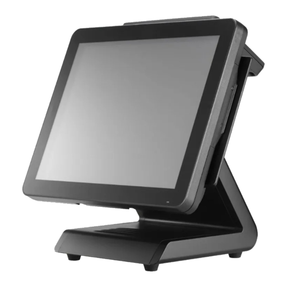
Identifying components This section describes the parts and connectors on the machine. Front-right view Figure 1.2 Front-right view Component Description 15-inch TFT LCD LED Power Indicator IO Panel HDD Compartment Power Button C H A P T E R 1 G E T T I N G S T A R T E D... -
Page 11: Figure 1.3 Rear View
Rear view Figure 1.3 Rear view Component Description MSR (optional) Slot HDD Compartment (for wall mounting) VFD Customer Display (optional) Slot Cable Compartment... -
Page 12: Figure 1.4 Sp-1030 I/O Connectors
I/O connectors Figure 1.4 SP-1030 I/O connectors Connector Description USB 2.0 ports VGA port COM 1 port USB 3.0 ports RJ-11 cash drawer port DC 12V input connector DC 12V output connector (for PM-116) Microphone jack Audio output jack COM 3 port... -
Page 13: Connector Pin Define
Connector pin define This section describes the connectors pin define. COM connector pin define Signal Signal SOUT VGA connector pin define Signal Signal Signal AGND Green AGND DDC DAT Blue AGND Horizontal Sync Vertical Sync DDC CLK USB 2.0 connector pin define Signal USB Vcc USB -... - Page 14 USB 3.0 connector pin define Signal Signal USB Vcc StdA_SSTX- USB - GND_DRAIN USB + StdA_SSRX+ USB GND StdA_SSRX- StdA_SSTX+ LAN connector pin define Signal Signal TXA+ TXC- TXA- TXB- TXB+ TXD+ TXC+ TXD- RJ-11 Cash Drawer connector pin define Signal CASEOPEN2 CASH1...
- Page 15 DC 12V input connector pin define Signal DC 12V output connector pin define Signal +12V SATA connector pin define Signal Signal SATA_RX- SATA_TX+ SATA_RX+ SATA_TX-...
- Page 16 C H A P T E R 1 G E T T I N G S T A R T E D...
-
Page 17: Chapter 2 Bios Setup
CHAPTER 2 BIOS SETUP The primary function of the BIOS (Basic Input and Output System) is to identify and initiate component hardware. The BIOS parameters are stored in non-volatile BIOS memory (CMOS). CMOS contents don’t get erased when the computer is turned off. The following topics are described in this chapter. •... -
Page 18: Entering The Setup Utility
Entering the Setup Utility When you power on the system, BIOS enters the Power-On Self Test (POST) routines. POST is a series of built-in diagnostics performed by the BIOS. After the POST routines are completed, the following message appears: Press DEL to run Setup Press the delete key <Delete>... -
Page 19: Using Bios
Using BIOS When you start the Setup Utility, the main screen appears. The main screen of the Setup Utility displays a list of the options that are available. A highlight indicates which option is currently selected. Use the cursor arrow keys to move the highlight to other options. -
Page 20: Main Screen
Main Screen This screen includes System BIOS Information, Processor, System memory and displays the System Time and System Date. Figure 2.2 Main Screen System Overview This screen displays System BIOS Information, Processor, System memory, System Time and System Date. System Time/ System Date The System Time and System Date items show the current date and time held by the machine. -
Page 21: Advanced Settings
Advanced Settings This setup screen includes sub-menus for APCI Configuration, CPU Configuration, SATA Configuration, USB Configurations, Super IO Configurations and Hardware Health Configuration. Figure 2.3 Advanced Settings Screen... -
Page 22: Acpi Settings
ACPI Settings Figure 2.4 ACPI Settings sub-menu Enable Hibernation This item allows user to enable or disable the hibernation feature for OS. This option may be not effective with some OS. ACPI Sleep State Use this item to define how the system suspends. In the default, S1 only (CPU Stop Clock), the suspend mode is equivalent to a software power down. -
Page 23: Cpu Configuration
CPU Configuration Figure 2.5 CPU Configuration sub-menu Hyper-threading This item enables or disables for Windows XP and Linux (OS optimized for Hyper-Threading Technology) and Disabled for other OS (OS not optimized for Hyper-Threading Technology). When setting this item “Disabled” only one thread per enabled core is enabled. Active Processor Cores This feature allows you to increase or decrease the number of active processor cores. -
Page 24: Sata Configuration
SATA Configuration Figure 2.6 SATA Configuration sub-menu SATA Controller(s) Use this item to enable or disable the on-chip SATA controller. The default setting is Enabled. SATA Mode Selection This item is used to configure SATA mode. The default setting is IDE. Aggressive LPM Support This item is used to enable aggressive LPM (link power management) support. -
Page 25: Usb Configuration
USB Configuration Figure 2.7 USB Configuration sub-menu Legacy USB Support When enabled, the BIOS will enable legacy support for USB keyboards, mice and floppy drives. You will be able to use these USB devices even with operating systems that do not support USB. USB3.0 Support This item enables or disables USB3.0 (XHCI) controller support. -
Page 26: Super Io Configuration
Super IO Configuration Figure 2.8 Super IO Configuration sub-menu PS2 Mouse Controller This item enables or disables PS2 Port. Serial Port x Voltage select This item allows you to set voltage for a serial port. Watch Dog Degree This item allows you to determine the functional degree of Watch Dog. Watch Dog Timer When select any time period, the Watchdog Timer will be enabled after that time period passes, every time the system boots up. -
Page 27: Serial Port X Configuration
Serial Port x Configuration Figure 2.9 Serial Port x Configuration sub-menu Serial Port x This item allows you to enables or disables a serial port. Change Settings This item allows you to specific IO address and IRQ for the serial port. -
Page 28: H/W Monitor
H/W Monitor Figure 2.10 Hardware Monitor sub-menu ShutDown Temperature This item allows setting the shutdown temperature. Once enabled, the machine will automatically shutdown when the temperature reaches the limit specified. C H A P T E R 2 B I O S S E T U P... -
Page 29: Cpu Ppm Configuration
CPU PPM Configuration Figure 2.11 CPU PPM Configuration sub-menu EIST This item allow you to enable or disable EIST (Enhanced Intel Speedstep Technology). When enabled, CPU will reduce power consumption. CPU C3 Report This item is used to enable or disable CPU C3 report to OS. CPU C6 Report This item is used to enable or disable CPU C6 report to OS. -
Page 30: Chipset Settings
Chipset Settings This screen allow you to configure the chipset options. Figure 2.12 Chipset Settings Screen System Agent (SA) Configuration Figure 2.13 System Agent (SA) Configuration sub- menu C H A P T E R 2 B I O S S E T U P... -
Page 31: Pch Io Configuration
PCH IO Configuration Figure 2.14 PCH IO Configuration sub-menu Onboard LAN Use this item to enable or disable the onboard LAN controller. The default setting is Enabled. Onboard LAN OPROM This feature allows you to enable or disable the onboard LAN boot ROM to boot system. Mini PCI Express Port This item allows you to enable or disable the Mini PCI Express device. -
Page 32: Usb Configuration
USB Configuration Figure 2.15 USB Configuration sub-menu XHCI Pre-Boot Driver This item enables or disables XHCI Pre-Boot Driver support. XHCI Mode This item sets the mode of operation of XHCI controller. EHCI1, EHCI2 These item allow you to enable or disable USB 2.0 support. C H A P T E R 2 B I O S S E T U P... -
Page 33: Graphics Configuration
Graphics Configuration Figure 2.16 Graphics Configuration sub-menu GTT Size This field allows you to select how much system memory can be allocated to GTT. Aperture Size This field allows you to select how much system memory can be allocated to graphics chip for video purposes. - Page 34 Spread Spectrum clock Chip When the motherboard clock generator pulses, the extreme values (spikes) of the pulses creates EMI (Electromagnetic Interference). The Spread Spectrum function reduces the EMI generated by modulating the pulses so that the spikes of the pulses are reduced to flatter curves. If you do not have any EMI problem, leave the setting at Off for optimal system stability and performance.
-
Page 35: Memory Configuration
Memory Configuration Figure 2.17 Memory Configuration sub-menu Memory Frequency Limiter This item allows you to set the maximum frequency of system memory. Max TOLUD This field allows you to select the maximum value of TOLUD. Dynamic assignment would adjust TOLUD automatically based on largest MMIO length of installed graphic controller. -
Page 36: Security Settings
Security Settings This screen allows you to configure the system security settings. Figure 2.18 Security Settings Screen Create or Change Adminitrator/ User Password An administrator password takes precedence over a user password, and the administrator can limit the activities of a user. To create or change a password, follow these steps: 1. -
Page 37: Boot Settings
Boot Settings This screen allow you to configure the boot options. Figure 2.19 Boot Settings Screen Setup Prompt Timeout This item allows you to select the number of seconds to wait for setup activation key. Bootup Numlock State This item is used to select the Power-on state for Numlock. Full Logo Screen display This item enables you to show the full screen logo on the bootup screen. -
Page 38: Save & Exit
Save & Exit This screen allows you to load default setting values, save changes and discard changes. Figure 2.20 Save & Exit Screen Discard Changes and Exit Highlight this item and press <Enter> to discard any changes that you have made in the Setup Utility and exit. When the dialog box appears, press <Yes>... -
Page 39: Chapter 3 Installing Drivers And Software
Use an external CD-ROM drive to install the drivers or copy the drivers to a USB flash drive and then plug to the machine. When you insert the CD ROM the following screen appears. Check SP-1030 that is listed under the “Install Terminal Drivers” and “Install Device Drivers” menus. -
Page 40: Intel Chipset Driver
Intel Chipset Driver The Intel Chipset Device Software updates the Windows XP/7 INF files so that the Intel chipset is correctly configured. Follow these instructions to install the chipset software : 1. Browse to the \DRIVER\chipset\Intel\Inf folder. 2. Double-click setup.exe. The following screen appears. Click Next to continue. 3. - Page 41 4. Browse the ReadMe Information, then click Next. 5. The Intel Chipset Software Utility files are installed to the system. When prompted to restart, select Yes, I want to restart my computer now. Then click Finish to restart the system.
-
Page 42: Intel Chipset Graphics Driver
Intel Chipset Graphics Driver This utility installs the Intel Extreme Graphics 2 drivers for Windows XP/2000. To install the drivers. 1. Browse to the \DRIVER\VGA\intel\ folder. 2. Double-click the executable file. The following screen appears. Click Next to continue. 3. Read the license agreement, then click Yes. C H A P T E R 3 I N S T A L L I N G D R I V E R S A N D S O F T W A R E... - Page 43 4. Browse the ReadMe Information, then click Next. 5. When installation is completed, select Yes, I want to restart my computer now. Then click Finish to restart the system.
-
Page 44: Lan Driver
LAN Driver The network driver support Windows XP/2000. Refer to the following to install the drivers. 1. Browse to the \DRIVER\LAN\RealTek folder. 2. Double-click the executable file. The following screen appears. Click Next to continue. 3. Click Install to begin installation. C H A P T E R 3 I N S T A L L I N G D R I V E R S A N D S O F T W A R E... - Page 45 4. When installation is completed, click Finish.
-
Page 46: Touch Screen Driver
Touch Screen Driver Refer to the following to install the touch screen driver. 1. Browse to the \DRIVER\Touch\eGalax folder. 2. Double-click setup.exe. The following screen appears. Click Next to continue. 3. Read the license agreement, check “I accept the term of the license agreement”. Click Next to continue. - Page 47 4. Check the box for Install PS/2 interface drive and then click Next to continue. 5. System will give you a warning, click OK to continue. 6. Uncheck the box for Install RS232 interface drive and then click Next to continue.
- Page 48 7. Check the box for None and then click Next to continue. 8. System will give you a warning, click OK to continue. 9. Uncheck the box for Support Mulit-Monitor System and then click Next to continue. C H A P T E R 3 I N S T A L L I N G D R I V E R S A N D S O F T W A R E...
- Page 49 10. Click Next to continue. 11. Click Next to continue.
- Page 50 12. Click Next to continue. 13. Click Yes, I want to restart my computer now and then click Finish. C H A P T E R 3 I N S T A L L I N G D R I V E R S A N D S O F T W A R E...
-
Page 51: Calibrating The Touchscreen
Calibrating the touchscreen Follow these instructions to calibrate the touchscreen using the TouchKit application: 1. Launch the TouchKit application from the Windows desktop by clicking on Start > All Programs > eGalaxTouch > Configure Utility. 2. Select the Tools page. 3. - Page 52 5. Click OK to complete the 4 points calibration. You may also use this application to adjust the touch settings. NOTE C H A P T E R 3 I N S T A L L I N G D R I V E R S A N D S O F T W A R E...
-
Page 53: Chapter 4 Locating The Problem
CHAPTER 4 LOCATING THE PROBLEM Refer to this section to locate the problem with the machine. The following topics are described. • General checkout guidelines on the page 45 • Cash drawer checkout on the page 45 • LCD symptoms on the page 46 •... -
Page 54: Lcd Symptoms
Figure 4.1 Connecting a cash drawer Cashdrawer 2. Turn on the machine . Refer to the following to prevent incorrect cash drawer status detection by the system: Port I/O Port Address Condition Note Cashdrawer A High(1) → Close If Bit is set to Low to open the Control port cash drawer, after it must be set Low(0) →... -
Page 55: Touch Screen Symptoms
Touch screen symptoms Symptom Corrective Procedure • Touchscreen does not 1. Install and run the touchscreen calibration program from the driver function • No virtual mouse 2. Reseat the panel cable. • Cursor doesn’t follow when 3. Reseat the touchscreen board-to-touch panel cable. touching the screen 4. -
Page 56: Usb Symptoms
USB symptoms Symptom Corrective Procedure • USB device does not function 1. Check that the USB device is detected in Windows Device Manager. 2. Reinstall the USB device driver. 3. Replace the mainboard. Peripheral-device symptoms Symptom Corrective Procedure • USB ports do not work 1. -
Page 57: Mainboard Jumper
Mainboard jumper JLV3 JLV1 JCMOS1 JLV2 Figure 4.2 SP-1030 mainboard jumper Jumper Setting Description 1-2 (default) Voltage Switch Jumper for Cash Draw RJ-11 Connector 1-2 (default) Normal JCMOS1 Clear CMOS Clear... - Page 58 Jumper Setting Description 1-2 (default) CN17 USB Power selection 3.3V JP2/JP3 3-4 (default) RING Switch headers for COM3/COM4 pin9 JLV1 LCD backlight inverter power selection 2-3 (default) 1-2 (default) 3.3V JLV2 LCD panel power selection 1-2 (default) Voltage level mode JLV3 Backlight control mode selection PWM mode...
-
Page 59: Mainboard Connectors
12V-out port connector to connector to HDD power COM4 port Figure 4.3 SP-1030 mainboard connectors Panel control board connectors connector to mainboard connector to touch connector to touch panel panel Figure 4.4 SP-1030 panel control board connectors... - Page 60 C H A P T E R 4 L O C A T I N G T H E P R O B L E M...
-
Page 61: Chapter 5 Replacing Field Replaceable Units (Frus)
After replacing optional devices, make sure all screws, springs, or other small parts are in place and are not left loose inside the case. Metallic parts or metal flakes can cause electrical shorts. Only qualified personnel should perform repairs on the SP-1030. Damage due to unauthorized servicing is not covered by the warranty. -
Page 62: Before You Begin
CAUTION Before you begin Make sure you have a stable, clean working environment. Dust and dirt can get into the SP-1030 components and may cause malfunction. Adequate lighting and proper tools can prevent you from accidentally damaging the internal components. Most of the electrical and mechanical connections can be disconnected by using your fingers. -
Page 63: Msr
1. Remove two screws. 2. Disconnect the cable. 3. Remove the MSR. Customer Display 1. Remove two screws. 2. Disconnect the cable. 3. Remove the customer display. -
Page 64: Hdd
1. Rotate the LCD screen forward . 2. Press and the hard drive com- partment cover as it shown on the picture. 3. Turn the screw counterclockwise to loosen the hard drive tray. 4. Slide the hard drive tray. 5. Disconnect the power cable and SATA cable from the hard drive. -
Page 65: Sp-1030 Panel
SP-1030 Panel 1. Rotate the LCD screen forward . 2. Remove the screw that secure the base to the SP-1030. The screen is fragile. Placing the monitor face-down on a flat, soft area prevents CAUTION scratches, defacing, or breakage. 3. Disconnect cables from HDD. -
Page 66: Panel Back Cover
Panel Back Cover Before proceeding, remove the following FRUs. • “SP-1030 Panel” on page 1. Remove four screws. 2. Gently pull away the top of back cover, then open the back cover. C H A P T E R 5 R E P L A C I N G F I E L D R E P L A C E A B L E U N I T S ( F R U s ) -
Page 67: Speaker
Speaker Before proceeding, remove the following FRUs. • “SP-1030 Panel” on page 51. • “Panel Back Cover” on page 1. Remove two screws from the speaker bracket. 2. Remove four screws. 3. Disconnect the cable from the mainboard. 4. Remove the speaker. -
Page 68: Power Button
Power Button Before proceeding, remove the following FRUs. • “SP-1030 Panel” on page 51. • “Panel Back Cover” on page 1. Remove two screws from the power button bracket. 2. Remove two screws. 3. Disconnect the cable from the mainboard. -
Page 69: Heatsink
Heatsink Before proceeding, remove the following FRUs. • “SP-1030 Panel” on page • “Panel Back Cover” on page 52. 1. Remove four screws from the heatsink. 2. Remove the heat sink. CAUTION To avoid the heat sink clearance issue. When you... -
Page 70: Memory
Memory Before proceeding, remove the following FRUs. • “Panel Back Cover” on page 52. 1. Open the clips. 2. Pull out the memory module. Battery Before proceeding, remove the following FRUs. • “Panel Back Cover” on page 52. 1. Open the hock. 2. -
Page 71: Cpu
Before proceeding, remove the following FRUs. • “Panel Back Cover” on page 52. 1. Open the load lever. 2. Pull out the CPU. notches CAUTION When you replace Pin1 the CPU, align notches and Pin1 as shown. -
Page 72: I/O Shield
I/O Shield Before proceeding, remove the following FRUs. • “SP-1030 Panel” on page 51. • “Panel Back Cover” on page 1. Remove all screws from the I/O ports. 2. Remove two screws from the I/O shield. 3. Remove the I/O shield. -
Page 73: Mainboard
Mainboard Before proceeding, remove the following FRUs. • “SP-1030 Panel” on page 51. • “Panel Back Cover” on page • “Heatsink” on page 55. • “I/O Shield” on page 58. 1. Disconnect all cables from the mainboard. 2. Remove four screws. -
Page 74: Fan
3. Remove the fans. Panel Bracket Before proceeding, remove the following FRUs. • “SP-1030 Panel” on page 51. • “Panel Back Cover” on page • “Speaker” on page 53. • “Power Button” on page 54. • “Heatsink” on page 55. -
Page 75: Touch Panel, Lcd Panel
Touch Panel, LCD Panel Before proceeding, remove the following FRUs. • “SP-1030 Panel” on page • “Panel Back Cover” on page 52. • “Speaker” on page 53. • “Power Button” on page • “Heatsink” on page 55. • “I/O Shield” on page 58. - Page 76 C H A P T E R 5 R E P L A C I N G F I E L D R E P L A C E A B L E U N I T S ( F R U s )
-
Page 77: Appendix Part List And Specification
APPENDIX PART LIST AND SPECIFICATION Figure 6.1 Exploded diagram main parts... -
Page 78: Part List
Part list DESCRIPTION ITEM NO 2+3+4 6651500S00002 Touch panel 2619040310001 Glue 250814500S001 Panel cover 25000500S0108 TFT LCD/15” 2614550150011 Panel Bracket 21004500S0036 Mainboard 26105500S3000 Fan 40x40x28 2103000000145 Fan supporter 21004500S3002 Heatsink 2103200000010 IO Bracket 21004500S3001 MSR bracket 25003500M2105 MSR base 25002500M2001 MSR module 7005000001015 MSR cover... -
Page 79: Specifications
Specifications Item SP-1030 Intel IVY or Sandy LGA1155 CPU Celeron G540 2.5Ghz dual core, Ivy Bridge i3-3220 3.3 GHz dual core, Ivy Bridge i5-3550S 3.0 GHz Quad core Chipset Intel B75 chipset 15” LCD, resolution 1024 x 768 LED backlight... - Page 80 A P P E N D I X...
Need help?
Do you have a question about the SP-1030 and is the answer not in the manual?
Questions and answers