Table of Contents
Advertisement
Quick Links
Advertisement
Table of Contents

Related Manuals for Partner SP-2500 Series


Summary of Contents for Partner SP-2500 Series
- Page 1 POS Terminal SP-2500 Series Service Manual...
- Page 2 Regulatory Notices 警告 使用過度恐傷視力。 注意事項 使用 分鐘請休息 分鐘。未滿 歲幼兒不看螢幕, 歲以上每天看螢幕不要超過 小時。 WARNING This is Class A Product. In domestic environment this product may cause radio interference in which case the user may be required to take adequate measures. 警告使用者 這是甲類的資訊產品,在居住的環境中使用時,可能會造成射頻干擾,在這種情況下,使用者會被要 求採取某些適當的對策。...
- Page 3 Legislation and WEEE Symbol 2002/96/EC Waste Electrical and Electronic Equipment Directive on the treatment, collection, recycling and disposal of electric and electronic devices and their components. The crossed-out wheeled bin symbol on the device means that it should not be disposed of with other waste at the end of its working life.
-
Page 4: Regulatory Notices
Safety Information Computer components and electronic circuit boards can be damaged by discharges of static electricity. Working on computers that are still connected to a power supply can be extremely dangerous. Follow these guidelines to avoid damage to the computer or injury to yourself. •... - Page 5 Contact Information Partner Tech Corporation 10F., No.233-2, Baoqiao Rd., Xindian Dist., New Taipei City 231, Taiwan http://www.partner.com.tw/...
-
Page 6: Copyright And Trademark
Copyright and Trademark Copyright This publication, including all photographs, illustrations and software, is protected under international copyright laws, with all rights reserved. Neither this manual, nor any of the material contained herein, may be reproduced without written consent of the author. Disclaimer The information in this document is subject to change without notice. -
Page 7: Table Of Contents
Contents Regulatory Notices ......................2 Safety Information ......................3 Copyright and Trademark ....................4 About this manual ......................4 Chapter 1 Getting Started ....................7 Unpacking ........................7 Identifying Components ....................8 Connector Pin Define ......................9 Chapter 2 Locating the Problem ..................13 General Checkout Guidelines .................... -
Page 9: Chapter 1 Getting Started
Getting Started This chapter describes how to unpack and identifying components on the device. Unpacking It is a good idea to save the packaging materials and shipping box in case that machine needs to be returned for service. Please un-pack and re-pack the machine terminal as shown below. -
Page 10: Identifying Components
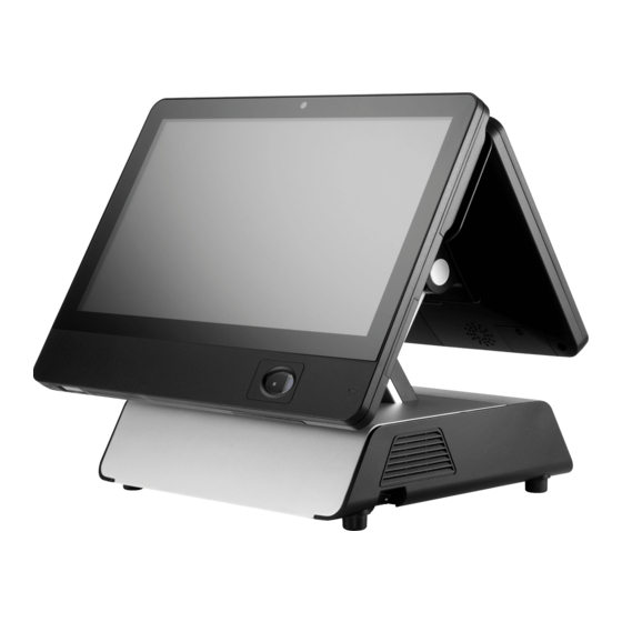
Identifying Components IC Reader 2D Scanner RFID iButton/ Fingerprint Dual Display 3 optional display sizes Power Button RJ-11 Cash drawer port I/O Panel USB 24V* USB 12V* COM2 COM4 Line-Out* MIC* VGA2* VGA1 DC12V-In USB 3.0 DC12V-Out COM1 COM3 USB 2.0 (* optional) -
Page 11: Connector Pin Define
Connector Pin Define This section describes the connectors pin define. COM Connector Pin Define Signal Signal SOUT *It could be supplied with power with 5V or 12V via Jumper or BIOS-setting. VGA Connector Pin Define Signal Signal Signal AGND Green AGND DDC DAT Blue... - Page 12 RJ-11 Cash Drawer Connector Pin Define Signal CASEOPEN2 CASH1 CASEOPEN1 CASH2 *Voltage is selected via JP1 DC 12V Input Connector Pin Define Signal LAN Connector Pin Define Signal Signal TXA+ TXC- TXA- TXB- TXB+ TXD+ TXC+ TXD- DC 12V Output Connector Pin Define Signal +12V...
- Page 13 USB 3.0 Connector Pin Define Signal Signal USB Vcc StdA_SSRX- USB - StdA_SSRX+ USB + USB GND StdA_SSTX- StdA_SSTX+ SATA Connector Pin Define Signal Signal SATA_RX- SATA_TX+ SATA_RX+ SATA_TX- USB 12V connector pin define Signal Signal +12V USB + +12V USB - USB Vcc USB 24V connector pin define...
-
Page 15: Chapter 2 Locating The Problem
Locating the Problem Refer to this section to locate the problem with the drvice. General Checkout Guidelines Use the following procedure to troubleshoot problems: • Identify as many symptoms as possible in detail. • Verify symptoms by recreating them. • Follow the corrective procedures in order. -
Page 16: Lcd Symptoms
Refer to the following to prevent incorrect cash drawer status detection by the system: I/O Port Port Condition Note Address High(1) → Close If Bit is set to Low to open Cashdrawer A 05A8 the cash drawer, after it Control port Low(0) →... -
Page 17: Touch Screen Symptoms
Touch Screen Symptoms Symptom Corrective Procedure • Touchscreen does not • Install and run the touchscreen calibration program from the function driver CD. • No virtual mouse • Reseat the panel cable. • Cursor doesn’t follow when • Reseat the touchscreen board-to-touch panel cable. touching the screen •... -
Page 18: Usb Symptoms
USB Symptoms Symptom Corrective Procedure • USB device does not function • Check that the USB device is detected in Windows Device Manager. • Reinstall the USB device driver. • Replace the mainboard. Peripheral-Device Symptoms Symptom Corrective Procedure • USB ports do not work •... -
Page 19: Chapter 3 Replacing Field Replaceable Units (Frus)
Replacing Field Replaceable Units (FRUs) This chapter provides instructions for replacing FRUs. Before You Begin Make sure you have a stable, clean working environment. Dust and dirt can get into components and may cause malfunction. Adequate lighting and proper tools can prevent you from accidentally damaging the internal components. -
Page 20: Hard Disk Drive
Hard Disk Drive Remove two manual screws. Remove the HDD bay cover. Remove the screw that secures the HDD tray to the base. Pull the HDD out of its bay. - Page 21 Remove four screws securing the HDD to its tray.
-
Page 22: Mainboard
Mainboard Remove two manual screws 2* manual screws and three screws. 3* screws Remove the base cover. Remove power switch cable... - Page 23 Remove speaker cable. Pull out the mainboard bracket.
-
Page 24: Add Second Hdd
Add Second HDD Before proceeding, remove the following FRUs. • Mainboard Flip the mainbord bracket. Pull the SATA connector through the hole in the mainboard bracket. Secure the SATA connector to the mainboard bracket. Connect the SATA cable... - Page 25 Secure the HDD with the HDD kit. Slide in the HDD tray to connect the SATA connector. Screw the SATA tray on the base.
-
Page 26: Assemble Front Screen
Assemble Front Screen Remove four screws to remove the arm cover. Secure the arm on the base cover with four screws. - Page 27 Plug the screen cable on the mainboard through the arm. Secure the base cover. Plug the screen cable on the front screen.
- Page 28 Hook front screen to the arm. Secure the front screen with two screws.
-
Page 29: Assemble Second Screen
Assemble Second Screen Remove four screws to remove the arm cover. Secure secondary arm on the primary arm with screws. Plug the screen cable on the mainboard through the arm. -
Page 30: Msr Reader
Secure the base cover. Assemble Front Screen and Rear Screen. MSR Reader Remove two screws to remove the MSR cover. Connect the MSR Reader cable to the screen. Secure the MSR Reader on the screen. -
Page 31: Ic Card Reader
IC Card Reader Remove one screw to remove the IC Card Reader cover. Connect the IC Card Reader cable to the screen. Secure the IC Card Reader on the screen. Fingerprint Remove one screw to remove the Fingerprint cover. Connect the Fingerprint cable to the screen. - Page 32 Install the Fingerprint. Secure the Fingerprint cover on the screen.
-
Page 33: I-Button
i-Button Remove one screw to remove the i-Button cover. Connect the i-Button cable to the screen. Put the cables into the compartment. Secure the i-Button cover on the screen. -
Page 34: 2D Scanner
2D Scanner Remove one screw to remove the 2D Scanner cover. Connect the 2D Scanner cable to the screen. Secure the 2D Scanner cover on the screen. -
Page 35: Appendix A Specification
Specification SP- 2500 SP- 2511 SP- 2515 SP- 2518 Item POS PC Touch Terminal Touch Terminal Touch Terminal ” ” ” 11 . 6 1366 x 768 15 . 6 1366 x 768 18 . 5 1366 x 768 Display Touch Projected capacitive touch (Multi Touch) Processor...
Need help?
Do you have a question about the SP-2500 Series and is the answer not in the manual?
Questions and answers