Table of Contents
Advertisement
Quick Links
Download this manual
See also:
Service Manual
Advertisement
Table of Contents

Related Manuals for Partner SP-1000-C


Summary of Contents for Partner SP-1000-C
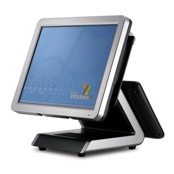
- Page 1 POS Terminal SP-1000-C User Manual...
-
Page 3: Declaration Of Conformity
Copyright This publication, including all photographs, illustrations and software, is protected under international copyright laws, with all rights reserved. Neither this manual, nor any of the material contained herein, may be reproduced without written consent of the author. Disclaimer The information in this document is subject to change without notice. The manufacturer makes no representations or warranties with respect to the contents hereof and specifically disclaims any implied warranties of merchantability or fitness for any particular purpose. -
Page 4: About This Manual
SP-1000-C serviced, and technical specifications. Safety information Before installing and using the SP-1000-C, take note of the following precautions: • Read all instructions carefully. • Do not place the unit on an unstable surface, cart, or stand. -
Page 5: Table Of Contents
Identifying components .................3 Connecting peripheral devices ...............6 Connecting a cash drawer ................7 Powering the machine on and off ..............8 Mounting the SP-1000-C on the wall .............9 CHAPTER 2 BIOS SETUP ............11 About the Setup Utility .................11 Entering the Setup Utility ................12 BIOS navigation keys ................12... - Page 6 APPENDIX .................. 35 Troubleshooting ...................35 Tips for Troubleshooting ................35 The Power-On Self Test ................35 Beep Errors at POST ...................35 Beep Message Errors at POST ..............36 General Problems ..................37 Having the SP-1000-C Serviced ..............38 Specifications ....................39...
-
Page 7: Chapter 1 Getting Started
CHAPTER 1 GETTING STARTED This chapter describes the procedures from unpacking the SP-1000-C, to powering it on. The following topics are described. • Unpacking the machine on page 1 • Checking the package contents on page 2 • Identifying components on page 3 • Connecting peripheral devices on page 6... -
Page 8: Checking The Package Contents
Checking the package contents After you unpack the device check that the following items are included. Driver CD with drivers and SP-1000-C the user manual PDF file. Adapter Power Cable If any item is missing or appears damaged, contact your dealer immediately. -
Page 9: Identifying Components
Identifying components This section describes the parts and connectors on the machine. Front-right view Figure 1.2 Front-right view Component Description 15-inch TFT LCD LED Power Indicator IO Panel HDD Compartment Power Button... -
Page 10: Rear View
Rear view Figure 1.3 Rear view Component Description MSR (optional) Slot HDD Compartment (for wall mounting) VFD Customer Display (optional) Slot Cable Compartment Do not block the air vents. No obstructions in 5 cm from the vents. CAUTION C H A P T E R 1 G E T T I N G S T A R T E D... - Page 11 I/O connectors Figure 1.4 SP-1000-C I/O connectors Connector Description VGA port COM 2 port USB ports RJ11 cash drawer port DC 12V input connector DC 12V output connector (for PM-116) Microphone jack Audio output jack COM 3 port COM 1 port...
-
Page 12: Connecting Peripheral Devices
Connecting peripheral devices Peripheral devices such as a printer or scanner can be connected to the machine. Refer to the user manual of the device you are connecting for instructions on installing drivers where needed. Adapter USB Compliant devices Cashdrawer PM-116 Monitor MR HS AA CD... -
Page 13: Connecting A Cash Drawer
Connecting a cash drawer Refer to the following to connect a cash drawer. The cash drawer RJ-11 connector is DC+24V. Ensure the cash drawer to be connected matches this power specification. IMPORTANT 1. Flip up the LCD panel, you can find the I/O panel is at the bottom of the LCD panel. -
Page 14: Powering The Machine On And Off
Powering the machine on and off Refer to the following to power on and off the machine. 1. Locate the I/O panel that is at the bottom of the machine. 2. Connect the adapter to the power cable, and then insert the power plug into an electrical outlet (AC100 - 240 V). -
Page 15: Mounting The Sp-1000-C On The Wall
Mounting the SP-1000-C on the wall The SP-1000-C can be attached to a wall mount (optional). 1. Turn off the power, and disconnect all power and peripheral cables. 2. Flip up the LCD panel. 3. Remove the screw that secure the base to the SP-1000-C. - Page 16 SP-1000-C with the hooks on the wall mount bracket. 6. Insert the hooks on the wall mount bracket into the mounting holes in the back of the SP-1000-C and slide the SP-1000-C down onto the bracket. 7. Reconnect the cables.
-
Page 17: Chapter 2 Bios Setup
CHAPTER 2 BIOS SETUP The primary function of the BIOS (Basic Input and Output System) is to identify and initiate component hardware. The BIOS parameters are stored in non-volatile BIOS memory (CMOS). CMOS contents don’t get erased when the computer is turned off. The following topics are described in this chapter. • About the Setup Utility on page 11 • Main Screen on page 14 • Advanced Settings on page 15... -
Page 18: Entering The Setup Utility
Entering the Setup Utility When you power on the system, BIOS enters the Power-On Self Test (POST) routines. POST is a series of built-in diagnostics performed by the BIOS. After the POST routines are completed, the following message appears: Press <F2> to enter SETUP Press the delete key <F2>... -
Page 19: Using Bios
Using BIOS When you start the Setup Utility, the main screen appears. The main screen of the Setup Utility displays a list of the options that are available. A highlight indicates which option is currently selected. Use the cursor arrow keys to move the highlight to other options. -
Page 20: Main Screen
Main Screen This screen includes System BIOS Information, Processor, System memory and displays the System Time and System Date. Figure 2.2 Main Screen System Time/ System Date The System Time and System Date items show the current date and time held by the machine. If you are running a Windows OS, these items are automatically updated whenever you make changes to the Windows Time and Date Properties utility. -
Page 21: Sata Port 1/ 2
SATA Port 1/ 2 Figure 2.3 SATA Port sub- menu Type This item automatically detect hard disk drive. The BIOS Setup automatically fills in the correct values for the remaining fields on this sub-menu. LBA Format LBA Format for a hard disk > 512 MB under DOS and Windows. Total Sectors Displays the total number of sectors. Maximum Capacity Displays the capacity of the hard disk. Multi-Sector Transfers This item will enhance hard disk performance by reading or writing more data during each transfer. -
Page 22: Intel Settings
Intel Settings This screen allow you to configure the Intel features. Figure 2.4 Intel Settings screen CK-505 Clock Chip: This item allows user to select control programming of the CK-505 clock chip. PLL3 Spread Spectrum Mode This item is used to On/Off Spread Spectrum support for PLL3 in the CK-505 clock chip. QuickBoot Mode Enabling this setting will cause the BIOS power-on self test routine to skip some of its tests during booting for faster system boot. -
Page 23: Cpu Control Sub-Menu
CPU Control Sub-Menu Figure 2.5 CPU Control sub-menu Core Multi-Processing This option is used to select the number of CPU core . Hyper Threading Technology This item is used to enable/ disable Hyper Threading Technology. Turbo Mode This item is used to enable/ disable Turbo Mode. Intel(R) SpeedStep(tm) This item is used to enable/ disable Intel SpeedStep, that allow the clock speed of the processor to be dynamically changed by software. -
Page 24: Pch Control Sub-Menu
PCH Control Sub-Menu Figure 2.6 PCH Control sub-menu PXE OPROM This item is used to enable/ disable PXE Option ROMs. Wake-On-Lan (WOL) This item is used to enable/ disable Wake-On-Lan, that allows the system to be woken up by a network message. -
Page 25: Pci Express Control Sub-Menu
PCI Express Control Sub-Menu Figure 2.7 PCI Express Control sub-menu PCI Express - Root Port This feature is used to enable/ disable the PCI Express Root Port. -
Page 26: Lpc Control Sub-Menu
LPC Control Sub-Menu Figure 2.8 LPC Control sub-menu C H A P T E R 2 B I O S S E T U P... -
Page 27: Sio Control Sub-Menu
SIO Control Sub-Menu Figure 2.9 SIO Control sub-menu COM 1/ 2/ 3/ 4/ 5/ 6 Configuration: COM: These items are used to enable/ disable the COM port 1/ 2/ 3/ 4/ 5/ 6. ADDR: These items are used to assign the I/O address for the COM port 1/ 2/ 3/ 4/ 5/ 6. IRQ: These items are used to assign the IRQ for the COM port 1/ 2/ 3/ 4/ 5/ 6. - Page 28 IRQ: This item is used to assign the IRQ for the LPT port. LPT Mode: This item allows user to select the LPT port mode. C H A P T E R 2 B I O S S E T U P...
-
Page 29: H/W Monitor Sub-Menu
H/W Monitor Sub-Menu Figure 2.10 H/W Monitor Sub-Menu Backlight Control This item allow user to control the backlight brightness. Chassis Intrusion This item is used to enable/ disable chassis intrusion, this feature can alert you when your computer chassis is opened. -
Page 30: Amt Sub-Menu
AMT Sub-Menu Figure 2.11 AMT sub-menu UnConfigure ME: This item is used to enable/ disable the function of Intel UnConfigure ME. MeFwDowngrade: This item is used to enable/ disable the function of Intel MeFwDowngrade. C H A P T E R 2 B I O S S E T U P... -
Page 31: Keyboard Feature Sub-Menu
Keyboard Feature Sub-Menu Figure 2.12 Keyboard Feature Sub-Menu NumLock: This function is used to set the state of the keyboard’s numlock function after POST. Typematic Rate Setting This feature allows you to gain manual control of the keystroke repeat feature. -
Page 32: Security Settings
Security Settings This screen allows you to configure the system security settings. Figure 2.13 Security Settings screen Supervisor/ User Password Indicates whether a supervisor/ user password has been set. If the password has been installed, Set displays. If not, Clear displays. Set Supervisor/ User Password These items can be used to install a password. A Supervisor password takes precedence over a User password, and the Supervisor can limit the activities of a User. -
Page 33: Boot Settings
Boot Settings This screen allow you to configure the boot options. Figure 2.14 Boot Settings screen Boot priority order: Set the boot device options to determine the sequence in which the computer checks which device to boot from. -
Page 34: Exit Menu
Exit Menu This screen allows you to load the default values, and save or discard changes. Figure 2.15 Exit Menu screen Exit Saving Changes Highlight this item and press <Enter> to save the changes that you have made in the Setup Utility and exit the Setup Utility. - Page 35 Save Changes Highlight this item and press <Enter> to save the changes that you have made in the Setup Utility. When the dialog box appears, select <Yes> to save changes, or select <No> to return to the menu.
- Page 36 C H A P T E R 2 B I O S S E T U P...
-
Page 37: Chapter 3 Upgrading Components
CHAPTER 3 UPGRADING COMPONENTS This chapter describes how to upgrade components for the SP-1000-C. The following topics are described. • Safety and precautions on page 37 • Before you begin on page 38 • Upgrading the hard drive on page 39 Safety and precautions Computer components and electronic circuit boards can be damaged by discharges of static electricity. -
Page 38: Before You Begin
Before you begin Make sure you have a stable, clean working environment. Dust and dirt can get into components and may cause malfunction. Adequate lighting and proper tools can prevent you from accidentally damaging the internal components. Most of the electrical and mechanical connections can be disconnected by using your fingers. It is recommended that you do not use needle-nosed pliers to disconnect connectors as these can damage the soft metal or plastic parts of the connectors. -
Page 39: Upgrading The Hard Drive
Upgrading the hard drive Refer to the following to remove and replace the hard drive. 1. Turn off the device properly through the operating system. 2. Disconnect the power cord from the power outlet. 3. Press and the hard drive compartment cover as it shown on the picture. - Page 40 C H A P T E R 3 U P G R A D I N G C O M P O N E N T S...
-
Page 41: Appendix
If failure is detected in an area other than the mainboard (such as the keyboard or an adapter card), an error message is displayed on the screen and testing is stopped. If your system does not successfully complete the POST, but displays a blank screen, have the SP-1000-C serviced. -
Page 42: Beep Message Errors At Post
Replace the battery. FAILED The battery may be weak. Replace the battery. CMOS CHECKSUM ERROR The CMOS may be corrupt. Have the SP-1000-C serviced. HARD DISK(S) FAIL (80) HDD reset failed. Have the SP-1000-C serviced. HDD controller diagnostics HARD DISK(S) FAIL (40) Have the SP-1000-C serviced. -
Page 43: General Problems
Refer to the following general problems you may encounter. PROBLEM SOLUTION The display screen is dark. Make sure that the SP-1000-C is not in suspend mode. An incorrect date and time are displayed. Correct the date and time using the DOS DATE and TIME commands or the options in the Setup Utility. -
Page 44: Having The Sp-1000-C Serviced
Having the SP-1000-C Serviced If you are unable to solve the problem, you should have the terminal serviced. Pack the terminal in the original carton. (See “Unpacking the SP-1000-C” on page 1.) Include a description of the problem and a checklist of the steps you took when trying to fix the problem. The information may be useful to the service personnel. -
Page 45: Specifications
Specifications Intel Celeron P4500 Intel Core i5-520M Intel Core i7-620M CPU Type (2M Cache 1.86Ghz) (3M Cache 2.40Ghz) (4M Cache 2.66Ghz) 15” Active TFT color LCD, resolution 1024 x 768 Touch 5-wire Resistive touch (PS2 interface) Memory 204pin DDR3 SO-DIMM 1GB (up to 4 GB) Ethernet 10/100M/1G Storage... - Page 46 3 tracks magnetic reader Customer display module (2 x 20 VFD) Optional 1 * Mini PCI-e support WiFi function Peripherals Biometric Reader, Smart Card Reader, I-Button, RFID reader 2nd monitor(Dual screen) Operation Windows 7, Windows XP Pro, WEPOS/POSReady, Linux (ubuntu), OPOS & JPOS System Power Supply AC100~240V/DC12V, 7.5A, 90 watt power adaptor...
Need help?
Do you have a question about the SP-1000-C and is the answer not in the manual?
Questions and answers