
Subscribe to Our Youtube Channel
Related Manuals for Teknik Boulevard Cafe 5420667


Summary of Contents for Teknik Boulevard Cafe 5420667
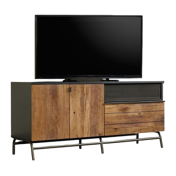
- Page 1 Teknik Your holder for all things awesome. Credenza Boulevard Cafe Collection | Model 420667 NOTE: THIS INSTRUCTION BOOKLET CONTAINS IMPORTANT SAFETY INFORMATION. PLEASE READ AND KEEP FOR FUTURE REFERENCE.
- Page 2 Table of Contents Assembly Tools Required Part Identifi cation No. 2 Phillips Screwdriver Tip Shown Actual Size Hardware Identifi cation Assembly Steps 5-28 Hammer Not actual size Safety Skip the power trip. This time. WARNING Use of a TV that is too heavy or large is hazardous. A TV that is too heavy will create a risk of a tip-over that can cause severe injury or death.
- Page 3 Now you know Part Identifi cation our ABCs. å While not all parts are labeled, some of the parts will have a label or an inked letter on the edge to help distinguish similar parts from each other. Use this part identifi cation to help identify similar parts. RIGHT END (1) SHELF (1) LEFT DRAWER SIDE (1)
- Page 4 Hardware Identifi cation å Screws are shown actual size. You may receive extra hardware with your unit. LARGE HIDDEN SMALL HIDDEN EXTENSION SLIDE - 2 EXTENSION RAIL - 2 CAM - 18 CAM - 6 (EXTENSION SET SHOWN SEPARATED) WOOD THREADED ANGLED HEAD STRAIGHT HEAD...
- Page 5 Step 1 Assemble your unit on a carpeted fl oor or on the empty å carton to avoid scratching your unit or the fl oor. Push eighteen LARGE HIDDEN CAMS (3) into the å ENDS (A and B), BACK (D), UPRIGHT (E), and SHELF (H). Arrow (18 used) Arrow...
- Page 6 Step 2 Fasten the HINGE BRACKETS (12) to the LEFT END (B) and å UPRIGHT (E). Use the screws in the HINGE BRACKETS. NOTE: Be sure to use the exact holes shown. å Page 6...
- Page 7 Step 3 Turn eighteen ANGLED HEAD CAM SCREWS (5) into the å ENDS (A and B), TOP (C), and UPRIGHT (E). Angled head (18 used) Page 7...
- Page 8 Step 4 Fasten the DOOR RAILS (G) to the RIGHT END (A) and å UPRIGHT (E). Use six BLACK 1" FLAT HEAD SCREWS (19). Fasten the DOOR STOPS (10) to the RIGHT END (A) and å UPRIGHT (E). Use four BLACK 1/2" PAN HEAD SCREWS (23). BLACK 1/2"...
- Page 9 Step 5 Separate the EXTENSION SLIDES (2) from the å EXTENSION RAILS (1) as shown in the upper diagram Just think. The sooner below. Be prepared, the parts are greasy. you do this, the sooner you do something else. Fasten the EXTENSION RAILS (1) to the RIGHT END (A) and å...
- Page 10 Step 6 Insert three WOOD DOWELS (7) into the BACK (D). å Fasten the UPRIGHT (E) to the BACK (D), by placing the å back edge of the UPRIGHT over the WOOD DOWELS (7). The DOOR RAIL (G) should be here. Page 10...
- Page 11 Step 7 Insert two WOOD DOWELS (7) into the UPRIGHT (E). å Fasten the SHELF (H) to the UPRIGHT (E). Tighten two å HIDDEN CAMS. NOTE: Be sure the WOOD DOWELS in the UPRIGHT å insert into the holes in the SHELF. The HIDDEN CAMS should be closer to this edge S u r...
- Page 12 Step 8 Insert two WOOD DOWELS (7) into the LEFT END (B). å Fasten the LEFT END (B) to the BACK (D). Tighten two HIDDEN CAMS. å NOTE: Be sure the WOOD DOWELS in the LEFT END insert into the BACK (D). å...
- Page 13 Step 9 Insert nine WOOD DOWELS (7) into the edges of the å ENDS (A and B), BACK (D) and UPRIGHT (E). Fasten the BOTTOM (I) to the ENDS (A and B), BACK å (D) and UPRIGHT (E). Use ten BLACK 1-1/2" FLAT HEAD SCREWS (18).
- Page 14 Step 10 With the help of another person, carefully stand your å unit upright. Insert nine WOOD DOWELS (7) into the TOP (C). å Fasten the TOP (C) to the ENDS (A and B), BACK (D), and å UPRIGHT (E). Tighten eight HIDDEN CAMS. Caution Two person lift required...
- Page 15 Step 11 Fasten the REAR LEG (J) to the FRONT LEG (K). Use three å BLACK 1/2" ALLEN HEAD SCREWS (20) and the ALLEN WRENCH (25). BLACK 1/2" ALLEN HEAD SCREW (3 used in this step) Page 15...
- Page 16 Step 12 Caution With the help of another person, carefully fl ip your unit å onto its TOP (C). Fasten the LEGS (J and K) to the BOTTOM (I). Use six å Two person BLACK 1-1/2" ALLEN HEAD SCREWS (17) and the lift required ALLEN WRENCH (25).
- Page 17 Step 13 With the help of another person, carefully turn your unit å onto its BACK (D). Side Step: Make nachos. (Optional, but 1. Turn a THREADED PIN (9) into the RIGHT END (A) as å recommended.) shown below. 2. Place the FLIP-UP DOOR (N) over the THREADED PIN (9) å...
- Page 18 Step 14 Push six SMALL HIDDEN CAMS (4) into the large holes in å the DRAWER SIDES (O and R) and DRAWER BRACE (S). Arrow Hole Arrow The arrow in the HIDDEN (6 used) CAM must point toward the hole in the edge of the board. Page 18...
- Page 19 Step 15 Turn six STRAIGHT HEAD CAM SCREWS (6) into the å DRAWER FRONT (T). Straight head (6 used) Page 19...
- Page 20 Step 16 f a c s u r n i s h U n fi Groove Fasten the DRAWER SIDES (O and R) and DRAWER å Slide a DRAWER BOTTOM (Q) into the grooves å BRACE (S) to the DRAWER FRONT (T). Tighten six in the DRAWER SIDES (O and R) and DRAWER FRONT (T).
- Page 21 Step 17 Fasten the EXTENSION SLIDES (2) to the å DRAWER SIDES (O and R). Use six BLACK 1/2" PAN HEAD SCREWS (23). Fasten the PULL (16) to the DRAWER FRONT (T). Use four å BLACK 1/2" FLAT HEAD SCREWS (22). Open end Use these holes.
- Page 22 Step 18 Carefully stand your unit upright. å To insert the drawer into your unit, line up the EXTENSION å SLIDES on the drawer with the EXTENSION RAILS on the unit and push the drawer into the unit until the drawer is fully inserted.
- Page 23 Step 19 Fasten the HINGES (13) to the DOORS (L and M). Use å eight SILVER 1/2" FLAT HEAD SCREWS (21). SILVER 1/2" FLAT HEAD SCREW (8 used in this step) Page 23...
- Page 24 Step 20 Fasten the HINGES on the DOOR (L) to the HINGE å BRACKETS on the LEFT END (B). Follow the large diagram below fastening both HINGES å to the HINGE BRACKETS keeping the DOOR vertical at all times. Repeat this step fastening the RIGHT DOOR (M) to the å...
- Page 25 Step 21 Fasten the PULLS (15) to the DOORS (L and M). Use four å BLACK 1/2" FLAT HEAD SCREWS (22). Hey! It's starting to look like something! BLACK 1/2" FLAT HEAD SCREW (4 used for the PULLS) Page 25...
- Page 26 Step 22 Refer to the enlarged diagram to identify the parts on the HINGES. å The DOORS may need some adjustments. Follow the text below to make needed adjustments. å DOOR ADJUSTMENTS: å To adjust the DOORS from side to side (horizontal), turn the adjusting screw in or out. To adjust the DOORS up and down (vertical), loosen both vertical adjustment screws.
- Page 27 Step 23 Apply the WARNING LABEL (24) to the TOP (C). You should be able to read the label when the TV is removed å from the unit. When the TV is in place, it should hide the label. Peel off the backing and apply the label as shown in the diagram.
- Page 28 Step 24 Peel a CAM COVER from the CAM COVER CARD (14) and å stick one onto each visible HIDDEN CAM. Push two GROMMETS (11) into the holes in the BACK (D). å NOTE: Please read the back pages of the instruction å...
- Page 29 WARNING Please use your furniture correctly and safely. Improper use can cause safety hazards, or damage to your furniture or household items. Carefully read the following safety information. Death or serious injury may occur when children climb on audio and/or video equipment furniture. A remote control or toys placed on the furnishing may encourage a child to climb on the furnishing and as a result may tip over onto the child.
Need help?
Do you have a question about the Boulevard Cafe 5420667 and is the answer not in the manual?
Questions and answers