
Related Manuals for Teknik Boulevard Cafe 5420650


Summary of Contents for Teknik Boulevard Cafe 5420650
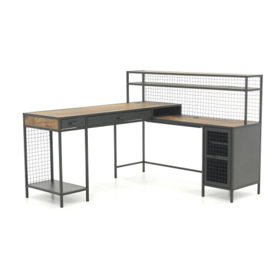
- Page 1 Teknik www.teknikoffice.co.uk For all your newfangled gadgetry. Boulevard Cafe L-Shaped Desk Model 5420650 NOTE: THIS INSTRUCTION BOOKLET CONTAINS IMPORTANT SAFETY INFORMATION. PLEASE READ AND KEEP FOR FUTURE REFERENCE.
- Page 2 Table of Contents Assembly Tools Required Part Identifi cation No. 2 Phillips Screwdriver Tip Shown Actual Size Hardware Identifi cation Assembly Steps 5-38 Hammer Not actual size Français 39-43 Straight Edge Screwdriver Español 44-48 Safety 49-50 Skip the power trip. This time.
- Page 3 Now you know Part Identifi cation our ABCs. å While not all parts are labeled, some of the parts will have a label or an inked letter on the edge to help distinguish similar parts from each other. Use this part identifi cation to help identify similar parts. LARGE RIGHT END (1) BACK (1) CC REAR RIGHT TUBE (1)
- Page 4 Hardware Identifi cation å Screws are shown actual size. You may receive extra hardware with your unit. (EXTENSION SET SHOWN SEPARATED) LARGE CAM LARGE HIDDEN EXTENSION RAIL - 4 EXTENSION SLIDE - 4 CAM - 28 SCREW - 14 SMALL CAM WOOD METAL SMALL HIDDEN...
- Page 5 Step 1 Assemble your unit on a carpeted fl oor or on the empty carton to å avoid scratching your unit or the fl oor. Push twenty-eight LARGE HIDDEN CAMS (3) into the SMALL å ENDS (C and D), SMALL UPRIGHTS (H and I), BACKS (J and L), BOX FRONT (R), BOX ENDS (Q and S), and BOX BOTTOM (T).
- Page 6 Step 2 Turn fourteen LARGE CAM SCREWS (4) into the exact holes å shown in the TOPS (F and G), SMALL RIGHT UPRIGHT (H), and BOX FRONT (R). Push ten SMALL HIDDEN CAMS (5) into the DRAWER å SIDES (FF, GG, JJ, and KK) and LARGE DRAWER BRACE (NN). Arrow (10 used) The arrow in the HIDDEN...
- Page 7 Step 3 Turn twenty-four SMALL CAM SCREWS (6) into the exact å holes shown in the SMALL RIGHT END (C), LARGE TOP (G), SHORT TUBES (AA), and DRAWER FRONTS (DD and EE). NOTE: The SMALL CAM SCREWS are turned into the metal å...
- Page 8 Step Step 4 Fasten the LARGE LEFT END (B) to the LARGE WIRE å BACK (N). Tighten two BLACK 1-3/8" HEX HEAD Just think. The sooner SCREWS (16) using the L-WRENCH (14). you do this, the sooner you do something else. BLACK 1-3/8"...
- Page 9 Step Step 5 NOTE: Be sure to keep SCREWS (19) separate from å SCREWS (22). Do not confuse these SCREWS. Fasten the SHELF TUBES (P) to the LONG SHELVES (M). å Use fi fteen BLACK 1/2" LARGE HEAD SCREWS (19). NOTE: Be sure SHELF TUBES wrap around the edges of å...
- Page 10 Step Step 6 Fasten the LONG SHELF (M) with one SHELF TUBE (P) to å the LEFT END (B). Tighten one BLACK 1-3/8" HEX HEAD SCREW (16) using the L-WRENCH (14). Fasten the LONG SHELF (M) to the LARGE WIRE BACK (N). å...
- Page 11 Step Step 7 Fasten the LONG SHELF (M) with two SHELF TUBES to å the LEFT END (B). Tighten two BLACK 1-3/8" HEX HEAD SCREWS (16) using the L-WRENCH (14). e w s s c r i t h f a c S u r BLACK 1-3/8"...
- Page 12 Step Step 8 Fasten the FRONT RIGHT TUBE (BB) to the SMALL TOP (F). å Use fi ve BLACK 1/2" LARGE HEAD SCREWS (19). NOTE: Be sure the FRONT RIGHT TUBE wraps around the å edge of the SMALL TOP. Fasten the MAGNETIC CATCH (10) to the block on the å...
- Page 13 Step Step 9 Fasten the BOX ENDS (Q and S) to the BOX FRONT (R). å Use four BLACK 1-1/2" FLAT HEAD SCREWS (17). Insert two WOOD DOWELS (7) into the SMALL TOP (F). å Fasten the BOX FRONT (R) and BOX ENDS (Q and S) to å...
- Page 14 Step Step 10 Insert two WOOD DOWELS (7) into the BOX FRONT (R). å Fasten the BOX BOTTOM (T) to the BOX FRONT (R). å Tighten three HIDDEN CAMS. NOTE: Be sure the WOOD DOWELS in the BOX FRONT å insert into the BOX BOTTOM.
- Page 15 Step Step 11 Fasten the SMALL TOP (F) to the LEFT END (B). Tighten one å BLACK 1-3/8" HEX HEAD SCREW (16) using the L-WRENCH (14). Fasten the SMALL TOP (F) to the LARGE WIRE BACK (N). Use å fi ve BLACK 1/2" LARGE HEAD SCREWS (19). BLACK 1/2"...
- Page 16 Step Step 12 NOTE: Do not completely tighten the SCREWS in this step. å Don't worry. It isn't Fasten the BACK (O) and RIGHT BOTTOM (V) to the å Rome. This can be built LARGE RIGHT END (A). Tighten fi ve BLACK 1/2" HEX in a day.
- Page 17 Step Step 13 NOTE: Do not completely tighten the SCREWS in this step. å Fasten the SHORT RIGHT TUBES (Y) to the RIGHT END (A). å Tighten two BLACK 1-3/8" HEX HEAD SCREWS (16) using the L-WRENCH (14). BLACK 1-3/8" HEX HEAD SCREW (2 used in this step) Page 17...
- Page 18 Step Step 14 Fasten the LARGE UPRIGHT (E) to the BACK (O). Tighten three BLACK 1/2" å HEX HEAD SCREWS (20) using the L-Wrench (14). Fasten the LARGE UPRIGHT (E) to the RIGHT BOTTOM (V). Tighten two å BLACK 1/2" HEX HEAD SCREWS (20) using the L-Wrench (14). Fasten the LARGE UPRIGHT (E) to the SHORT RIGHT TUBES (Y).
- Page 19 Step Step 15 NOTE: Start all of the SCREWS before completely å tightening any of them. Fasten the LARGE RIGHT END (A) to the SMALL TOP (F) å and LONG SHELVES (M). Tighten six BLACK 1-3/8" HEX HEAD SCREWS (16) using the L-Wrench (14). BLACK 1-3/8"...
- Page 20 Step Step 16 Fasten the REAR RIGHT TUBE (CC) to the LARGE LEFT END (B). Tighten å one BLACK 1-3/8" HEX HEAD SCREW (16) using the L-Wrench (14). Fasten one METAL BRACKET (8) to the LARGE UPRIGHT (E) and REAR å...
- Page 21 Step Step 17 Separate the EXTENSION SLIDES (2) from the EXTENSION RAILS (1) as shown in the upper diagram below. Be å prepared, the parts are greasy. Fasten two EXTENSION RAILS (1) to the SMALL ENDS (C and D). Use six BLACK 1/2" PAN HEAD SCREWS (22). å...
- Page 22 Step Step 18 Carefully fl ip the SMALL RIGHT END (C) over. å Fasten one EXTENSION RAIL (1) to the SMALL RIGHT END (C). å Use three BLACK 1/2" PAN HEAD SCREWS (22). NOTE: For each EXTENSION RAIL, turn a SCREW into the hole å...
- Page 23 Step Step 19 Fasten the SHORT BACK (J) to the SMALL WIRE BACK (K). å Use two BLACK 1-1/2" FLAT HEAD SCREWS (17). Now might be a good time to refresh your drink. BLACK 1-1/2" FLAT HEAD SCREW (2 used in this step) Page 23...
- Page 24 Step Step 20 NOTE: Start all of the SCREWS before completely tightening any of them. å Fasten the SMALL WIRE BACK (K) to the SMALL LEFT END (D). Tighten two å BLACK 1-3/8" HEX HEAD SCREWS (16) using the L-Wrench (14). Fasten the LEFT BOTTOM (W) to the SMALL LEFT END (D).
- Page 25 Step Step 21 NOTE: Start all of the SCREWS before completely tightening any of them. å Fasten the SMALL RIGHT END (C) to the SMALL WIRE BACK (K) and SHORT å LEFT TUBES (X). Tighten four BLACK 1-3/8" HEX HEAD SCREWS (16) using the L-Wrench (14).
- Page 26 Step Step 22 Fasten the SHORT TUBES (AA) to the SMALL UPRIGHTS (H and I). å Tighten two HIDDEN CAMS. Fasten one EXTENSION RAIL (1) to the SMALL LEFT UPRIGHT (I). Use å three BLACK 1/2" PAN HEAD SCREWS (22). NOTE: For each EXTENSION RAIL, turn a SCREW into the hole å...
- Page 27 Step Step 23 Insert one WOOD DOWEL (7) into the short edge of the å SMALL LEFT UPRIGHT (I). Fasten the SMALL LEFT UPRIGHT (I) to the LONG BACK (L). å Use one BLACK 1-1/2" FLAT HEAD SCREW (17). NOTE: Be sure the WOOD DOWEL in the SMALL LEFT å...
- Page 28 Step Step 24 NOTE: Use extra care in this step while lifting and placing å the assembled parts from Step 23 into the hutch part of the desk. Fasten the SMALL UPRIGHTS (H and I) to the SMALL å TOP (F). Use four BLACK 2-1/4" PAN HEAD SCREWS (15). NOTE: You may need to loosen and then retighten some å...
- Page 29 Step 25 NOTE: Do not lift up on the LONG BACK (L). å With someone's help, carefully stand the two assemblies upright. å Fasten the SMALL RIGHT END (C) to the LONG BACK (L). å Tighten two HIDDEN CAMS. NOTE: Do not lift up on the LONG BACK (L).
- Page 30 Step 26 Fasten the LONG LEFT TUBE (Z) to the FRONT RIGHT å TUBE (BB) on the SMALL TOP (F). Tighten one BLACK 1/2" HEX HEAD SCREW (20) using the L-Wrench (14). Fasten one METAL BRACKET (8) to the LONG LEFT å...
- Page 31 Step 27 Insert two WOOD DOWELS (7) into the SMALL RIGHT END (C) å and SMALL LEFT UPRIGHT (I). Fasten the LARGE TOP (G) to the SMALL ENDS (C and D), å SMALL UPRIGHTS (H and I), and BACKS (J and L). Tighten fourteen HIDDEN CAMS.
- Page 32 Step 28 With your straight edge screwdriver, turn four SHELF å PINS (9) into the hole locations of your choice in the Almost time to LARGE RIGHT END (A) and LARGE UPRIGHT (E). Set celebrate! With a nap. the SHELF (U) onto the SHELF PINS. (4 used) Page 32...
- Page 33 Step 29 Fasten the DOOR (OO) to the LARGE RIGHT END (A). å Use four BLACK 1/2" FLAT HEAD SCREWS (21). Insert three GROMMETS WITH CAPS (11) into the large å holes in the TOPS (F and G). BLACK 1/2" FLAT HEAD SCREW (4 used in this step) Page 33...
- Page 34 Step 30 Surface with HIDDEN CAMS Groove Fasten the LARGE DRAWER SIDES (JJ and KK) and LARGE DRAWER BRACE (NN) to the LARGE DRAWER å FRONT (DD). Tighten six HIDDEN CAMS. Peel the APPLIQUES from the BLACK APPLIQUE CARD (13) and stick them onto each HIDDEN CAM. å...
- Page 35 Step 31 Groove Fasten the SMALL DRAWER SIDES (FF and GG) to the SMALL DRAWER FRONT (EE). Tighten four HIDDEN CAMS. å Peel the APPLIQUES from the BLACK APPLIQUE CARD (13) and stick them onto each HIDDEN CAM. å With the palm of your hand, tap the DRAWER BOTTOM down into the groove.
- Page 36 Step 32 Fasten two EXTENSION SLIDES (2) to the LARGE å DRAWER SIDES (JJ and KK). Use six BLACK 1/2" PAN HEAD SCREWS (22). Open end Use these holes. Open end BLACK 1/2" PAN HEAD SCREW (6 used in this step) Open end Page 36...
- Page 37 Step 33 Fasten two EXTENSION SLIDES (2) to the SMALL å DRAWER SIDES (FF and GG). Use six BLACK 1/2" PAN HEAD SCREWS (22). Open end Use these holes. Open end BLACK 1/2" PAN HEAD SCREW (6 used in this step) Open end Page 37...
- Page 38 Step 34 To insert a drawer into your unit, line up the EXTENSION SLIDES on the drawer with the EXTENSION RAILS on the å unit and push the drawer into the unit until the drawer is fully inserted. The drawer will push in hard until it is all the way in, then it will slide in and out easier.
- Page 39 WARNING Please use your furniture correctly and safely. Improper use can cause safety hazards, or damage to your furniture or household items. Carefully read the following chart. Look out for: What can happen: How to avoid the problem: • Overloaded shelves or drawers. •...
Need help?
Do you have a question about the Boulevard Cafe 5420650 and is the answer not in the manual?
Questions and answers