
Related Manuals for Anest Iwata ALS-333 C


Summary of Contents for Anest Iwata ALS-333 C
- Page 1 USE and MAINTENANCE INSTRUCTION MANUAL • ALS-423 TX AIRLESS • ALS-333 C UNITS • ALS-433 C HIGH PRESSURE • ALS-433 TX...
-
Page 2: Table Of Contents
CONTENTS USE OF THE MANUAL ........................3 WARRANTY ........................... 3 SAFETY PRECAUTIONS ....................... 4 TRANSPORT AND HANDLING ..................... 6 TRANSPORT ........................... 6 TRANSPORT WITH CARDBOARD PACKING ................6 HANDLING ............................6 CHECK ON THE PURCHASED PRODUCT ..................7 TEMPORARY STORAGE ........................ 7 PRODUCT IDENTIFICATION ...................... -
Page 3: Use Of The Manual
MANUFACTURING COMPANY. WARRANTY All ANEST IWATA products have a one-year guarantee from the invoice date, unless otherwise stated in writing. The warranty covers all manufacturing faults and material defects. Any spare part replace- ment or repair operations are covered only if they are carried out by our technicians at our servicing shops. -
Page 4: Safety Precautions
1. SAFETY PRECAUTIONS • Be sure to read and understand this instruction manual. The operator shall be fully conver sant with the requirements stated within this instruction manual including important warnings, cautions and operations. • Wrong operation (mishandling) can cause serious bodily injury, death, fire or explosion. SAFETY FACTOR •... - Page 5 IMPORTANT Never alter the equipment When you replace parts, be sure to always use ANEST IWATA original spare parts. If not done, it can cause insufficient performance or failure. Install or keep pump free from rain or splashes. If not done, it can cause pump failure Install pump on a horizontal surface Install pump free of paint mist.
-
Page 6: Transport And Handling
2. TRANSPORT AND HANDLING TRANSPORT To transport the equipment only the systems described below can be used. In any case make sure that the transport and lifting device can bear the weight of the equipment with its packaging. WARNING ALWAYS KEEP THE PACKAGING IN VERTICAL POSITION. WARNING IT IS ADVISABLE THAT THE STAFF IN CHARGE OF HANDLING THE EQUIPMENT WEAR PROTECTIVE GLOVES AND SAFETY SHOES. -
Page 7: Check On The Purchased Product
CHECK ON THE PURCHASED PRODUCT When you receive and before using the pump, make sure it has not been damaged during tran sport or storage. Also check that all standard components are inside the packaging. TEMPORARY STORAGE During transport and storage make sure the temperatures between 0 and 40° C are not exceeded. In case of storage, make sure the equipment is not put in places with an excessive humidity. -
Page 8: Product Identification
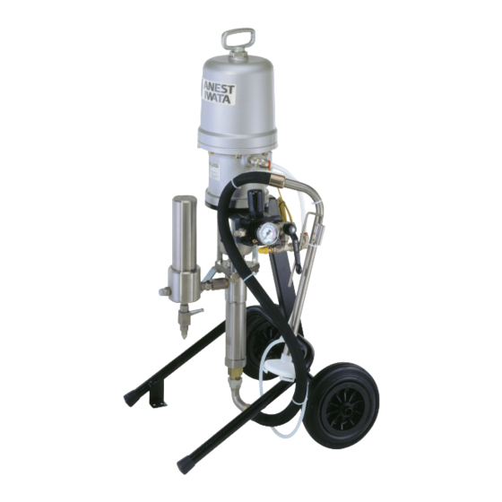
3. PRODUCT IDENTIFICATIONS PRODUCT SPECIFICATIONS ALS-333 C: STANDARD Version Pump unit PP1251 C mounted on cart, with air regulator, dip tube with filter, delivery paint filter unit, fluid recirculation hose , overpressure valve . ALS-433 C: STANDARD Version Pump unit PP4301 C mounted on cart, with air regulator, dip tube with filter, delivery paint filter unit, fluid recirculation hose , overpressure valve . -
Page 9: Plate Data
RATIO SERIAL NO. Max. working air pressure 0.68 MPa / 6.8 bar / 98 psi 25:1 ANEST IWATA Strategic Center S.r.l. MANUFACTURED C.so Vigevano,46 10155 Torino Italy COMPLIANCE TO THE STANDARDS All the units are conceived in compliance with the applicable Essential Safety Requirements of the Machinery Directive 2006/42/EC. -
Page 10: Safety Systems
SAFETY SYSTEM Several safety systems have been conceived during the Airless unit design and manufacture to safeguard the operator, as it prescribed by all applicable safety regulations. SAFETY INFORMATION In case of units that are to be used in areas with potentially explosive atmospheres, before starting working the operators must disable the unit power supply, by putting it “out of order”. -
Page 11: Workable Products
SELF. WORKABLE PRODUCTS All Airless Units ANEST IWATA are conceived to paint ferrous material in general, wood and plastic. Models ALS 333 C and ALS 433 C are designed for paints with a maximum viscosity of 85 sec/Ford #4 (100 sec/NK-2). We don't recommend the use of these models with water-based paints. -
Page 12: Operation
4. FUNZIONAMENTO OPERATION DESCRIPTION Airless pumps are composed of two main parts: the pneumatic motor and the pumping unit. The pneumatic motor is provided with an internal valve system for changing the movement direction. The pumping unit is composed of an anti-wear chromium plated suction body (liner) and a rod. The gaskets can be adjusted. -
Page 13: Installation And Starting-Up
5. INSTALLATION AND STARTING CONDITION FOR INSTALLATION • The installer must know the ATEX classification of the installation area, as well as the risks coming from a potentially explosive atmosphere, by paying attention to the explosion and fire risks so as to adopt the most suitable protections. - Page 14 INSTALLATION SCHEME PIC. 2 SAFETY SPRING PAINT OUT- UPPER GASKETS ADJUSTING RECIRCULATION CUP (D) VALVE (C) GROUND CABLE MATERIAL RECIR- CULATION HOSE (B) PAINT INLET SUCTION HOSE AIR INLET TROLLEY FASTENING BRACKET...
-
Page 15: Use
- If the system is used improperly, it could be broken by causing serious damage. - Use the Airless unit for professional purposes only. - Do not change the system; use only Anest Iwata original spare parts. - Check the system daily: repair or replace immediately all worn or damaged parts. -
Page 16: Upper Gaskets Prewash And Adjustment
PREWASH AND ADJUSTMENT OF UPPER PACKING 1. Make sure the pump has been properly installed; (see point 5.2) 2. Immerse dip tube (pos. 5 on page 26) in the cleaning liquid (clean solvent or water, according to the purchased model). 3. -
Page 17: Daily Interruptions
Never remove the gun trigger safety catch. c) Never exceed the maximum working pressure (6.8 bar). d) Always use a Airless ANEST IWATA gun, which is provided with various safety devices. e) During functioning, never touch the moving parts. Before carrying out any maintenance operation disconnect the air supply and discharge the residual pressure. -
Page 18: Wrong And Dangerous Uses
WRONG AND DANGEROUS USES A wrong earthing, an insufficient ventilation, a naked flame or a spark can cause a fire or an explosion and provoke some serious injuries. WARNING IF SOME SPARKS OR AN ELECTRIC DISCHARGE WERE PERCEIVED, INTERRUPT IMMEDIATELY ALL PAINTING OPERATIONS. -
Page 19: Maintenance And Inspection
7. MAINTENANCE AND INSPECTION GENERALS NOTE • Comply with the inspection and ordinary maintenance intervals so as to ensure suitable working conditions and explosion-proof protection. • Before carrying out any maintenance operation or repair on the internal parts, delay the opening of the unit and wait till it is completely cool to avoid any burning risk due to the presence of hot parts. -
Page 20: Disassembly And Re-Assembly Procedure
DISASSEMBLY AND RE-ASSEMBLY PROCEDURE WARNING BEFORE STARTING ANY MAINTENANCE OPERATION REMOVE THE AIR SUPPLY HOSE AND MAKE SURE THE INNER RESIDUAL PRESSURE HAS BEEN RELEASED. NOTE: The numbering of the follows components refers to the exploded view drawings of Airless Unit in chapter 8.0. -
Page 21: Motor Group Re-Assembly
MOTOR RE-ASSEMBLY Follow the above mentioned procedure in reverse order, bearing in mind the following points: 1. While assembling the valves (23), push the change-over body (7) downwards. Then, screw the valves to the change-over bar (12) and adjust the clearance between the sealing surfa-ces of the valves and of the piston (18), that must be equal to 2 mm for both. -
Page 22: Pump Rod Disassembly
PUMP ROD DISASSEMBLY 1. Secure the suction main body (47), unscrew the suction tube (58) and slip it off. 2. Slip the rod (39) off from suction main body (47). 4. Loosen the adjustment nut (50) and unscrew the valve holder (56). 5. -
Page 23: Motor Group Re-Assembly To The Pump Rod
7.12 MOTOR RE-ASSEMBLY TO THE PUMP ROD 1. In order to align the two parts (pneumatic motor and pump rod) in the best position, it is advisable to tighten the three nuts (49) and the suction tube (58) completely, with the pump running. (Air pressure 0.5 bar). -
Page 24: Spare Part Lists
8. SPARE PARTS LIST 8.1 ALS UNITS SPARE PARTS LIST PNEUMATIC MOTOR SPARES FLUID PUMP SPARES Ref. Description Ref. Description HANDLE THINNER CUP GASKET BUSHING ROD NUT FEMALE UPPER ADAPTER MOTOR NUT UPPER SPACER • O RING MALE UPPER ADAPTER AIR CYLINDER CONNECTION ROD •... -
Page 25: Exploded View
8.2 EXPLODED VIEW... -
Page 26: Accessories
9. ACCESSORIES 9.1 ACCESSORIES FOR ALS UNITS Ref. Description ALS-333 C ALS-433 C ALS-433 TX ALS-423 TX CART DELIVERY PAINT FILTER TF-8 TF-8 TF-8N TF-8N DIP TUBE WITH FILTER 50 MESH 50 MESH 30 MESH 30 MESH AIR REGULATOR SET 1/4"... -
Page 27: Delivery Filter Tf-8
9.2 DELIVERY PAINT FILTER TF-8 for ALS-333 C | ALS-433 C Ref. Description BODY CYLINDER FILTER HOLDER FILTER PLUG O RING FILTER 100 MESH JOINT R3/8” - R1/4” DRAIN VALVE G1/4”FF JOINT R1/4” - M8X6 F-10 JOINT R1/4”- G1/4” F-11 JOINT G1/4”M - R1/4”M... -
Page 28: Air Regulator Unit For Als 433-C / Als 433-Tx / Als 423-Tx
9.5 AIR REGULATOR SET for ALS-423 TX | ALS-433 C | ALS-433 TX Ref. Description PRESSURE GAUGE (OPTIONAL) AIR REGULATOR 3/8” SCREW JOINT PLATE NIPPLE R 3/8” BALL VALVE 3/8” REDUCTION 3-10 SAFETY VALVE 3-11 T JOINT FMF 3/8” 3-12 QUICK JOINT 3/8”... -
Page 29: Troubleshooting
10. TROUBLESHOOTING INCONVENIECE CAUSE CHECK SOLUTION The ball valve is not in the proper Make sure that the ball valve is in Adjust the ball valve in the proper position. the proper position. position. Check the proper functioning of the If it is closed, open it. - Page 30 6. The manometer indicates the presence of pressure Damaged air regulator. Replace it. even though the air regula- tor is closed. IMPORTANT: IN CASE OF REPLACEMENT ALWAYS USE GENUINE PARTS ANEST IWATA. Non original parts may compromise the Unit's operation.
-
Page 31: Dismantling
11. DISMANTLING 11.1 EQUIPMENT STORAGE If the Airless unit is to be stored for a certain period, the following operations are recommended: Disconnect the equipment from the energy sources. Remove all residues and deposits from the pump. Cover the equipment with a waterproof tarpaulin. 11.2 DISMANTLING If for any reason the pump is to be dismantled, some important rules have to be... - Page 32 ANEST IWATA Middle East FZE ANEST IWATA Deutschland GmbH Dubai - UNITED ARAB EMIRATES Leipzig - GERMANY info@anest-iwata-me.com info@anest-iwata.de www.anest-iwataeu.com www.anest-iwata.de ANEST IWATA Motherson Coating Equipment Ltd. ANEST IWATA France S.A. Noida - INDIA Saint Quentin Fallavier, Lyon - FRANCE sales@aim.motherson.com info@anest-iwata.fr www.motherson.com/anest-iwata-motherson.html www.anest-iwata.fr ANEST IWATA Russia LLC ANEST IWATA U.K.
Need help?
Do you have a question about the ALS-333 C and is the answer not in the manual?
Questions and answers