Table of Contents
Advertisement
Instruction Use and Maintenance Manual
AIRLESS UNITS
ALS 423 TX
ALS 333 C
ALS 433 C
ALS 433 TX
ALS 453 C
This ANEST-IWATA Airless Unit complies to ATEX regulations 94/9/EC.
Protection level: II 2 GX Suitable for use in Zones 1 and 2.
X marking:
Any static electricity discharge from the pump is to be diverted to the ground through
the grounding wire which is included in this product.
GB
ME0004ENRev.15
Advertisement
Table of Contents

Related Manuals for Anest Iwata ALS 423 TX


Summary of Contents for Anest Iwata ALS 423 TX
- Page 1 Instruction Use and Maintenance Manual AIRLESS UNITS ALS 423 TX ALS 333 C ALS 433 C ALS 433 TX ALS 453 C This ANEST-IWATA Airless Unit complies to ATEX regulations 94/9/EC. Protection level: II 2 GX Suitable for use in Zones 1 and 2.
- Page 2 ANEST IWATA EUROPE TORINO - ITALY The company ANEST IWATA EUROPE Srl mission is to supply all their product and spray painting equipment users and distributors with the STATE-OF-THE-ART of technology and with continuous innovations, to obtain the best finish at the lowest cost.
-
Page 3: Table Of Contents
AIRLESS UNIT ALS 433 C ......................34 AIRLESS UNIT ALS 433 TX ......................36 AIRLESS UNIT ALS 453 C ......................38 AIRLESS UNIT ALS 423 TX ......................40 ACCESSORIES ..........................42 9.1 / 9.2 / 9.3 / 9.4 - ALS ACCESSORIES ..................... 43 DELIVERY FILTER TF-8 ........................ -
Page 4: Use Of The Manual
Use of The use and maintenance manual is the document accompanying the equipment from its manufac- the manual ture till its dismantling. Therefore, it is an integral part of the equipment. The manual must be read before starting ANY ACTIVITY involving the equipment including its hand- ling. -
Page 5: Informative Letter
Other symbols Index of the use and maintenance manual Transport Description of the equipment Installation Ordinary use Wiring and hydraulic diagrams Dismantling Maintenance procedures Informative This use and maintenance manual is an integral part of the equipment and it must be easily availa- ble to the staff in charge of its use and maintenance. - Page 6 THIS USE AND MAINTENANCE MANUAL DOES NOT MAKE UP FOR ANY DESIGN INADEQUA- In case of breakdown or malfunction, apply to the CUSTOMER CARE SERVICE. USTOMER ERVICE ANEST IWATA EUROPE s.r.l C.so Vigevano, 46 - 10155 Torino Telephone +39 011.24.80.868 Telefax +39 011.85.19.44 E-mail: info@anest-iwataeu.com...
-
Page 7: Warranty
Warranty All ANEST IWATA s.r.l. products have a one-year guarantee from the invoice date, unless otherwi- se stated in writing. The warranty covers all manufacturing faults and material defects. Any spare part replacement or repair operations are covered only if they are carried out by our technicians at our servicing shops. -
Page 8: Transport And Handling
1. TRANSPORT AND HANDLING Transport To transport the equipment only the systems described below can be used. In any case make sure that the transport and lifting device can bear the weight of the equipment with its packaging. WARNING ALWAYS KEEP THE PACKAGING IN VERTICAL POSITION. WARNING IT IS ADVISABLE THAT THE STAFF IN CHARGE OF HANDLING THE EQUIPMENT WEAR PROTEC- TIVE GLOVES AND SAFETY SHOES. -
Page 9: Handling
Handling To handle the cardboard packaging use a trolley. To handle or displace the airless unit only use the handle. WARNING FOLLOW THE INSTRUCTIONS ON THE PACKAGING BEFORE HANDLING AND OPENING IT. HANDLING BY MEANS OF HANDLE HANDLING BY MEANS OF TROLLEY Temporary storage During transport and storage make sure the temperatures between 0 and 40°... -
Page 10: Product Identification
Pump type PP 4301 CNE on trolley with air adjustment, suction pipe, delivery and suction paint filter, fluid recirculation. ALS 423 TX: ALS 423 TX AIRLESS UNIT Pump type PP 4231 NE on trolley with air adjustment, suction pipe, delivery and suction paint filter, fluid recirculation. -
Page 11: Technical Specifications
Technical specifications ALS 333 C MODEL ALS 33 3C Pump type PP1251 C Dimensions (mm) 500x500x900 Weight 23 Kg Air pipe fitting G 1/4” Fluid pipe fitting G 1/4” Paint filter TF-8 Fluid suction filter 50 Mesh Max. air working pressure 6.8 bar Compression ratio 25:1... - Page 12 ALS 433 C MODEL ALS 433 C ALS 433 TX ALS 433 TX Pump type PP4301 C PP4301 CNE Dimensions (mm) 500x500x970 500x500x970 Weight 30 Kg 30 Kg Air pipe fitting G 1/4” G 1/4” Fluid pipe fitting G 1/4” G 1/4”...
- Page 13 ALS 453 C MODEL ALS 453 C Pump type PP4531 C Dimensions (mm) 500x500x970 Weight 30 Kg Air pipe fitting G 1/4” Fluid pipe fitting G 1/4” Paint filter TF 9 Fluid suction filter 50 Mesh Max. air working pressure 6.8 bar Compression ratio 53:1...
- Page 14 ALS 423 TX MODEL ALS 423 TX Pump type PP 4231 NE Dimensions (mm) 500x500x970 Weight 35 Kg Air pipe fitting G 1/4” Fluid pipe fitting G 1/4” Paint filter TF-8N Fluid suction filter 30 Mesh Max. air working pressure 6.8 bar...
-
Page 15: Safety Systems
Safety systems Several safety systems have been conceived during the airless unit design and manufacture to safeguard the operator, in compliance with pr EN 12621 Directive about paint. SAFETY INFORMATION In case of units that are to be used in areas with potentially explosive atmospheres, before starting working the operators must disable the unit power supply, by putting it “out of order”. -
Page 16: Workable Products
Models ALS 333 C, ALS 433 C and ALS 453 C are intended for solvent-based paints with a maximum viscosity of 85 sec/Ford #4 (100 sec/NK-2). Models ALS 423 TX and ALS 433 TX are intended for high viscosity thixotropic water-based paints. -
Page 17: Operation
3. OPERATION Operation description Airless pumps are composed of two main parts: the pneumatic motor and the pumping unit.The pneumatic motor is provided with an internal valve system for changing the movement direction. The pumping unit is composed of an anti-wear chromium plated suction body (liner) and a rod. The gaskets can be adjusted. -
Page 18: Installation And Starting-Up
4. INSTALLATION AND STARTING Check on the purchased product Before using the pump, make sure it has not been damaged during transport or storage. Also check that all standard components are inside the packaging. Conditions for installation • The installer must know the ATEX classification of the installation area, as well as the risks coming from a potentially explosive atmosphere, by paying attention to the explosion and fire risks so as to adopt the most suitable protections. -
Page 19: Cautions
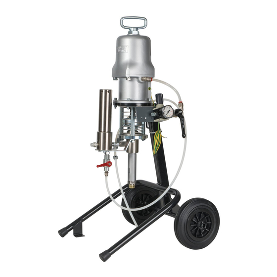
PICTURE 2 SAFETY SPRING PAINT OUTLET UPPER GASKETS ADJUSTING RECIRCULATION CUP (D) VALVE (C) GROUND CABLE MATERIAL RECIR- CULATION PIPE (B) PAINT INLET SUCTION PIPE AIR INLET TROLLEY FASTENING BRACKET Cautions Operate the pump with air filtered by means of an air filter with a filtering section smaller than 50 µm;... -
Page 20: Use
- If the system is used improperly, it could be broken by causing serious damage. - Use the airless unit for professional purposes only. - Do not change the system; use only Anest Iwata original spare parts. - Check the system daily: repair or replace immediately all worn or damaged parts. -
Page 21: Upper Gaskets Prewash And Adjustment
Prewash and adjustment of upper packing 1. Make sure the pump has been properly installed; (see point 4.3) 2. Immerse dip tube (pos. 5 on page 42) in the cleaning liquid (clean solvent or water, according to the purchased model). 3. -
Page 22: Daily Interruptions
Never remove the gun trigger safety catch. c) Never exceed the maximum working pressure (6.8 bar). d) Always use a airless ANEST IWATA gun, which is provided with various safety devices. e) During functioning, never touch the moving parts. Before carrying out any maintenance opera- tion, disconnect the air supply and discharge the residual pressure. -
Page 23: Wrong And Dangerous Uses
Wrong and dangerous uses A wrong earthing, an insufficient ventilation, a naked flame or a spark can cause a fire or an explosion and provoke some serious injuries. WARNING IF SOME SPARKS OR AN ELECTRIC DISCHARGE WERE PERCEIVED, INTERRUPT IMMEDIA- TELY ALL PAINTING OPERATIONS. -
Page 24: Pressure Release Process
Pressure release process WARNING 1. Close the air supply to the pump by turning the pressure reducer adjustment counter-clockwise down to 0 bar. 2. Activate the safety catch of the airless gun trigger. 3. Make sure the recirculation pipe is not clogged, then gradually open the recirculation ball valve, and leave it open. -
Page 25: Maintenance And Inspection
6. MAINTENANCE AND INSPECTION General notes • Comply with the inspection and ordinary maintenance intervals so as to ensure suitable working conditions and explosion-proof protection. • Before carrying out any maintenance operation or repair on the internal parts, delay the opening of the unit and wait till it is completely cool to avoid any burning risk due to the presence of hot parts. -
Page 26: Disassembly And Re-Assembly Procedure
Disassembly and re-assembly procedure WARNING BEFORE STARTING ANY MAINTENANCE OPERATION REMOVE THE AIR SUPPLY PIPE AND MAKE SURE THE INNER RESIDUAL PRESSURE HAS BEEN RELEASED. NOTE: The numbering of the follows components refers to the exploded view drawings of Airless Unit in chapter 8.0. -
Page 27: Motor Group Re-Assembly
Motor group re-assembly Follow the above mentioned procedure in reverse order, bearing in mind the following points: 1. While assembling the valves (23), push the change-over body (7) downwards. Then, screw the valves to the change-over bar (12) and adjust the clearance between the sealing surfa- ces of the valves and of the piston (18), that must be equal to 2 mm for both. -
Page 28: Pump Rod Disassembly
Moreover, check the wear conditions of all the other components and replace them if necessary. NOTE: For model ALS 423 TX the two sets of gaskets (pos. 46 and pos. 54) can also be composed of 6 or 8 gaskets. As a matter of fact, replacing the spacer (pos. 52 or pos. -
Page 29: Pump Rod Re-Assembly
6.11 Pump rod re-assembly Reverse the above mentioned procedure bearing in mind the following points: 1. Adjust the lower gaskets in order to obtain a “smooth sliding movement of the liner”. NOTE: If the gaskets are too tight their duration shall result extremely reduced. The regular and proper adjustment, together with suitable maintenance, ensures a long lasting duration of the gaskets. -
Page 30: Troubleshooting
7. TROUBLESHOOTING Inconvenience Cause Check Solution 1.The air pressure a) The ball valve is not a) Make sure the ball valve a) Adjust the ball valve does not increase in the proper position is in the proper position in the proper position. b) The air regulator b) Check the proper functioning b) If it is closed, open it. - Page 31 Inconvenience Cause Check Solution 4. The pump a) Some air got inside a) Make sure the dip tube is a) Tighten the dip tube fitting. does not stop the paint ducts properly connected b) Some air remains inside b) Make sure the paint is in good b) If the paint is in standard condi- the paint ducts conditions and that the dip tube...
-
Page 32: Exploded Views With Spare Part Lists
8. EXPLODED VIEWS WITH SPARE PART LISTS AIRLESS UNIT ALS 333 C Ref. Picture on the next page Posit. Description Posit. Description HANDLE GASKET • GASKET BALL ROD NUT LOWER VALVE ° MOTOR NUT O RING SAFETY SPRING AIR CYLINDER FLUID OUTPUT JOINT CHANGE-OVER BODY CHANGE-OVER PIVOT... - Page 33 PUMP TYPE PP1251 C...
-
Page 34: Airless Unit Als 433 C
AIRLESS UNIT ALS 433 C Ref. Picture on the next page Posit. Description Posit. Description HANDLE GASKET • GASKET BALL ROD NUT LOWER VALVE ° MOTOR NUT O RING AIR CYLINDER SAFETY SPRING CHANGE-OVER BODY FLUID OUTPUT JOINT CHANGE-OVER PIVOT SPRING SPRING SEAT CHANGE-OVER BAR... - Page 35 PUMP TYPE PP4301C...
-
Page 36: Airless Unit Als 433 Tx
AIRLESS UNIT ALS 433 TX Ref. Picture on the next page Posit. Description Posit. Description HANDLE GASKET • GASKET BALL ROD NUT LOWER VALVE ° MOTOR NUT O RING AIR CYLINDER PACKING CHANGE-OVER BODY NIPPLE G 3/4”M-G 1/2” F SAFETY SPRING CHANGE-OVER PIVOT FLUID OUTPUT JOINT SPRING... - Page 37 POMPA TIPO PP4301 CNE...
-
Page 38: Airless Unit Als 453 C
AIRLESS UNIT ALS 453 C Ref. Picture on the next page Posit. Description Posit. Description HANDLE GASKET • GASKET BALL ROD NUT LOWER VALVE ° MOTOR NUT O RING AIR CYLINDER SAFETY SPRING CHANGE-OVER BODY FLUID OUTPUT JOINT CHANGE-OVER PIVOT SPRING SPRING SEAT •... - Page 39 PUMP TYPE PP4531 C...
-
Page 40: Airless Unit Als 423 Tx
AIRLESS UNIT ALS 423 TX Ref. Picture on the next page Posit. Description Posit. Description HANDLE GASKET • GASKET BALL ROD NUT LOWER VALVE ° MOTOR NUT O RING SCREW AIR CYLINDER SPRING CHANGE-OVER BODY PACKING NIPPLE 3/4” M-1/2”F CHANGE-OVER PIVOT... - Page 41 PUMP TYPE PP4231 NE...
-
Page 42: Accessories
9. ACCESSORIES PICTURE 7... -
Page 43: 9.2 / 9.3 / 9.4 - Als Accessories
Posit. Description TF 9 PAINT FILTER DIP TUBE WITH GALVANISED STEEL CONNECTION - 50 MESH AIR REGULATOR GROUP (3/8”) ALS 423 TX Posit. Description TF-8N PAINT FILTER DIP TUBE WITH STAINLESS STEEL CONNECTION - 30 MESH AIR REGULATOR GROUP (3/8”) -
Page 44: Delivery Filter Tf-8
JOINT R 1/4”M8x6 F-10 JOINT RC 1/4” F-11 JOINT AP 1/4”-1/4” MM F-12 PLUG R 1/4” Fig.D DELIVERY FILTER TF-8N For ALS 423 TX and ALS 433 TX Posit. Description Pic. D BODY CYLINDER SCREW O RING FILTER 100 MESH JOINT R 1/4”... -
Page 45: Delivery Filter Tf 9
DELIVERY FILTER TF 9 Fig.E ALS 453 C Posit. Description Fig. E BODY CYLINDER SCREW O RING FILTER JOINT AP 3/8” GC_1/4” MM DRAIN VALVE A.P. 1/4” JOINT 1/4” M8x6 E-10 JOINT RC 1/4” E-11 JOINT AP 1/4” GC_1/4” MM E-12 PLUG... -
Page 46: 9.9 Air Regulation Units
NIPPLE G 1/4”MM 3-12 QUICK JOINT 1/4”M 3-14 PRESSURE GAUGE (OPTIONAL) AIR REGULATION GROUP FOR ALS 433 C - ALS 433 TX - ALS 423 TX - ALS 453 C Posit. Description PRESSURE GAUGE (OPTIONAL) AIR REGULATOR 3/8” SCREW JOINT PLATE NIPPLE R 3/8”... -
Page 47: Dip Tube With Filter
9.10 DIP TUBE GROUP WITH FILTER Posit. Description Pic. E TTHREE TYPES: DIP TUBE WITH GALVANISED STEEL CONNECTION (15x1 with 50 MESH filter) DIP TUBE WITH STAINLESS STEEL CONNECTION (15x1 with 50 MESH filter) DIP TUBE WITH STAINLESS STEEL CONNECTION (1/2”... - Page 48 PT. ANEST IWATA Indonesia Jakarta - INDONESIA www.anest-iwatasoutheastasia.com ANEST IWATA Iberica S.L. Badalona - Barcelona - SPAIN info@anest-iwata.es ANEST IWATA SOUTH-EAST ASIA CO., Ltd. www.anest-iwata.es Bangkok- THAILAND www.anest-iwatasoutheastasia.com info@anest-iwata.co.th ANEST IWATA Scandinavia AB. Partille, Göteborg - SWEDEN info@anest-iwata.se ANEST IWATA Motherson Coating Equipment Ltd www.anest-iwata.se...
Need help?
Do you have a question about the ALS 423 TX and is the answer not in the manual?
Questions and answers