Advertisement
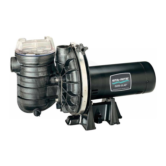
50 HZ. CENTRIFUGAL PUMPS WITH TRAP
Sta-Rite Industries, Inc., Export Sales & Marketing Group
293 Wright Street, Delavan, WI 53115 U.S.A.
TELEPHONE: (262) 728-5551, TELEFAX: (262) 728-4461, CABLE: STAREX TELEX: ITT 4970245
O
W
N
E
R '
INSTALLATION, OPERATION & PARTS
5PRA Series MODELS
1/2 HP
5PRA5C-180
3/4 HP
5PRA5D-195
1 HP
5PRA5E-182
1-1/2 HP
5PRA5F-184
S
M
A
N
U
5PRA5C3-180
5PRA5D3-195
5PRA5E3-182
5PRA5F3-184
5P2RA5YF-182
A
L
This manual should be furnished to
the end user of this pump; its use
will reduce service calls and chance
of injury and will lengthen pump life.
S3 (Rev. 9/6/05)
Advertisement

Related Manuals for STA-RITE 5PRA Series


Summary of Contents for STA-RITE 5PRA Series
- Page 1 Sta-Rite Industries, Inc., Export Sales & Marketing Group 293 Wright Street, Delavan, WI 53115 U.S.A. TELEPHONE: (262) 728-5551, TELEFAX: (262) 728-4461, CABLE: STAREX TELEX: ITT 4970245...
-
Page 2: Table Of Contents
To avoid unneeded service calls, prevent possible injuries, and get the most out of your pump, READ THIS MANUAL CAREFULLY! The Sta-Rite ‘5PRA’ Series Self-priming Centrifugal pump: • Is designed for use with swimming pools or as a centrifugal pump. -
Page 3: Safety Instructions
Check all clamps, bolts, lids, and system accessories before testing. Release all air in system before testing. Tighten Sta-Rite trap lids to 30 ft. lbs. (4.1 kg-m) torque for testing. Water pressure for test must be less than 25 PSI (7.5 kg/cm Water Temperature for test must be less than 100 F. -
Page 4: Installation
FIGURE 1 INSTALLATION Only qualified, licensed personnel should install pump and wiring. Pump mount must: Be solid - Level - Rigid - Vibration free. (To reduce vibration and pipe stress, bolt pump to mount.) Allow pump suction inlet height to be as close to water level as possible. Allow use of short, direct suction pipe (To reduce friction losses). - Page 5 Piping: Use at least 1-1/2" IPS PVC pipe with 5” trap. Use at least 2” pipe with 6” trap. Increase size if a long run is needed. To avoid strains on the pump, support both suction and discharge pipes independently. Place these supports near the pump. To avoid a strain left by a gap at the last connection, start all piping at the pump and run pipe away from the pump.
- Page 6 Suction Outlets Per Pump Provide at least two hydraulically balanced main drains, with covers (see Page 5), as suction outlets for each circulating pump suction line. The cen- ters of the main drains (suction outlets) on any one line must be at least three feet apart.
-
Page 7: Electrical
ELECTRICAL Ground motor before connecting to electrical power supply. Failure to ground motor can cause severe or fatal electrical shock hazard. Do not ground to a gas supply line. To avoid dangerous or fatal electrical shock, turn OFF power to motor before working on electrical connections. - Page 8 Bonding Grounding/Bonding: Install, ground, bond and wire motor according to local or National Electrical Code requirements. Green Ground Permanently ground motor. Use green ground terminal provided under Screw motor canopy or access plate (See Figure 3A); use size and type wire required by code.
-
Page 9: Operation
OPERA TION NEVER run pump dry! Running pump dry may damage seals, causing leakage and flooding! Fill pump with water before starting motor. Before removing trap cover: 1. STOP PUMP before proceeding. 2. CLOSE GATE VALVES in suction and discharge pipes. 3. -
Page 10: Pump Service
2. Remove trap cover and use low pressure air to blow accumulated water from the piping system. Use a Sta-Rite U79-11 Lid Wrench to remove trap covers that have been overtightened or have taken a set and cannot be removed by hand. - Page 11 3. Remove clamp holding pump halves together. 4. Remove pump base mounting bolts, if used. Motor and seal plate assem- bly can now be pulled away from pump body. 5. Remove five screws and washers holding diffuser to seal plate. Remove diffuser.
-
Page 12: Troubleshooting Guide
TROUBLESHOOTING GUIDE Read and understand safety and operating instructions in this manual before doing any work on pump! Only qualified personnel should electrically test pump motor! FAILURE TO PUMP; REDUCED CAPACITY OR DISCHARGE PRESSURE Suction leaks/lost prime: 1. Pump must be primed; make sure that pump volute and trap are full of water. -
Page 13: Repair Parts List
REPAIR PARTS LIST 5PRA SERIES POOL PUMP 1/2 through 1-1/2 H.P. Models 50 Hertz Single Phase Part Part Description Qty. Motor Chart at Right 2766 0197 Screw #10-32 x 1/2" U30-692SS Bonding Lug U17-568 Water Slinger 17351-0009 Seal Plate C103-193P... - Page 14 REPAIR PARTS LIST 5PRA SERIES POOL PUMP 1/2 through 1-1/2 H.P. Models 50 Hertz Three Phase Part Part Description Qty. Motor Chart at Right 2766 0197 Screw #10-32 x 1/2" U30-692SS Bonding Lug U17-568 Water Slinger 17351-0009 Seal Plate C103-193P...
- Page 15 REPAIR PARTS LIST MODEL 5P2RA5YF-182 2 SPEED POOL PUMP 1-1/2 H.P. Models 50 Hertz Single Phase Part Part Description Qty. 2766 0197 Motor J218-887A Screw #10-32 x 1/2" U30-692SS Bonding Lug U17-568 Water Slinger 17351-0009 Seal Plate C103-193P O-Ring U9-228A Shaft Seal U109-93SS Clamp...
- Page 16 5" TRAP/ADAPTER ASSEMBLY REPAIR PARTS LIST - 5" and 6" TRAPS* PKG. 115 Part No. Part Pkg. 115W Pkg. 161W Description 5" Trap 6" Trap Trap Cover C-139P1 16920-0011 O-Ring - Cover U9-229 16920-0012 Strainer Basket C108-33P 16920-0017 Trap Body C153-53P1W C53-60P Gasket...
Need help?
Do you have a question about the 5PRA Series and is the answer not in the manual?
Questions and answers