
Subscribe to Our Youtube Channel
Related Manuals for GDS 630P I Series

Summary of Contents for GDS 630P I Series
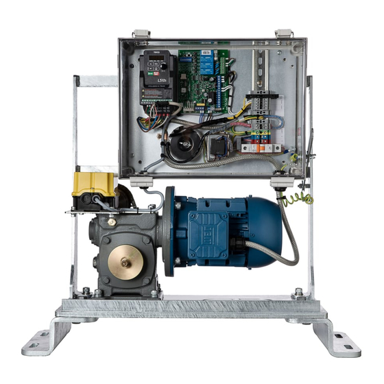
- Page 1 Installation and Maintenance Manual Sliding Gate Operators Inbuilt Models: GDS 450P I & 630P I Range Made in Australia from Australian & quality imported components MOVITRAC B A.B.N. 62 059 806 405 Oct 201 7 N14870...
-
Page 2: Abbreviated Installation Instructions
Abbreviated Installation Instructions (For those who don't have time!) S l i d i n g G a t e O p e r a t o r s PLC 450, 630 Range Made in Australia from Australian & quality imported components MOVITRAC B Place operator in correct position (Pinion wheel to be parallel to the gate and stepped out to allow for width of rack once it is mounted... - Page 3 Press the red commissioning button located next to the inverter and mode switch. (note-there should not be a present input on the open terminal from field wiring, this will prohibit the gate from closing, a momentary pulse is all that is required). Ensure the direction the gate first travels is toward the fully open position, if the gate first travels towards the closed position then turn the power off and reverse two of the motor wires at the...
-
Page 4: Table Of Contents
CONTENTS Section No: Page No: Abbreviated Installation Instructions Safety Precautions General Information Wiring Requirements Installation Details 6-11 Electrical Cabling Mechanical Installation Plan view of installation / Operator dimensions Electrical Connections Variable Speed Drive Unit Variable Speed Drive Unit - Key Pad Operation Function Factory Setting Parameter Settings Gate Direction Set-Up... -
Page 5: Safety Precautions
AFETY RECAUTIONS WARNING! FAILURE TO FOLLOW THESE SAFETY PRECAUTIONS AND INSTALLATION INSTRUCTIONS COULD RESULT IN INJURY OR DEATH AND OR DAMAGE TO PROPERTY AND EQUIPMENT Appropriately licensed and competent personnel only should install the automation equipment. The operators are designed specifically to open and close sliding gates or doors and should not be used for any other purpose. -
Page 6: General Information
Conduits and cabling preferably to enter through baseplate 'knockout' hole. The following dimensions will provide measurements for the positioning of Conduits and the appropriate position for the mounting of the operator, whether a GDS 450PI or a GDS 630PI. Mechanical Installation ... -
Page 7: Plan View Of Installation / Operator Dimensions
Plan View of Installation / Operator Dimensions... -
Page 8: Electrical Connections
Electrical Connections A 240v 10 amp Non Earth leakage protected power supply is required to power up the unit Electrical DIN rail terminal connections are as detailed below EARTH NEUTRAL ACTIVE CIRCUIT BREAKER Active (Filtered) Neutral (Filtered) Fuse (for 24v supply) 24V 3A Supply Gate running Output} - Gate running Output} + 24V 150mA... -
Page 9: Variable Speed Drive Unit
Operating Modes The thumbwheel selector switch is used to select the operation mode which best suits the customers purpose, the details of the operational modes are as follows: Mode “0” #Auto close, (1-120 seconds, set by the knob on the front of the keypad, fully clockwise is 120 second auto close time.) #PE auto close, (meaning that when the gate is fully open and the photo electric cell beam is broken and then made again the gate will close straight away) - Page 10 The diagram below (Figure 2) corresponds to what is shown on the keypad of the SEW variable speed drive (this keypad is removable). Figure 2. Function Factory Settings Acceleration ramp time 5 sec Deceleration ramp time 4 sec ...
-
Page 11: Gate Direction Set-Up
Selecting a Function To select a function use the up/down arrow keys to select corresponding symbol for desired function. An LED will light up the symbol and the display will show the programmed settings for that function. Setting Function Values ... -
Page 12: Fault Finding
AULT I NDI NG In the event that the operator does not function due to a fault or unmet condition, there is a simple and effective way of ascertaining where the probable fault may lie. As the invertor is a combination PLC that provides the logic for executing the running of the gate motor, the inputs and their status are very important. - Page 13 SEW Program with LED fault indication The fault status right hand led segment in P 35 will move up and down so many times according to what state each input is in. Some earlier model operators had a red led mounted in the back plate of the operator so the status of the operator could be seen without taking the cover off.
- Page 14 13 1 3...
-
Page 15: Manual Release
ANUAL ELEASE NSTRUCTIONS Place key in door lock, turn clockwise till released and pull door open Turn knurled knob anticlockwise approx. ½ a turn to release. With the clutch door open this disengages the door switch, which in turn inhibits the operation of the operator. Gate can now be opened by hand. -
Page 16: Maintenance
AINTENANCE ETAILS WARNING! Failure to maintain equipment may result in injury or death and/or damage to property and equipment Recommended maintenance to be performed on the operator and gate are as follows:- Operator performs over 150 cycles a day each month Operator performs between 100-150 cycles a day every 2 month Operator performs between 50-99 cycles a day... -
Page 17: Warranty
ARRANTY Gate Drive Systems Australia warrants that the goods manufactured by it shall be free from defect in manufacture for a period of 12 months from the date of invoice. Should any fault occur within that period as a result of faulty workmanship or materials, Gate Drive Systems Australia at its discretion, replace the product at no charge to the Customer except for removal, installation &...
Need help?
Do you have a question about the 630P I Series and is the answer not in the manual?
Questions and answers